Add Pop Out Bay Trusses
Framer
You can use this function to define a pop out bay truss area, and add trusses to it with even intervals. The slopes you select and the truss parameters will define the shape of the trusses.
- Select Modeling | Panel |
 Truss
Truss  Special
Trusses
Special
Trusses
 Pop-out Bay
Trusses.
Pop-out Bay
Trusses. - Select the truss parameters. The previously selected parameters are the default
parameters. You can reselect the parameters by using the function
 Edit truss
parameters in the auxiliary menu.
Edit truss
parameters in the auxiliary menu.
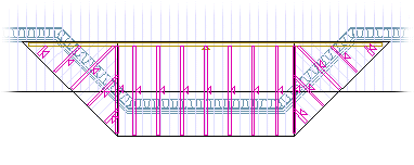
- Select the upper limiting structures, or the slopes of the bay window roof. Select several
slopes with the Ctrl key pressed down or by using area selection.
- If necessary, edit the truss area by adding or removing sections of roof slopes. You can select following functions from the auxiliary menu:
- Select Confirm.
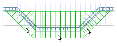
- Define the bottom chord of the trusses. Do one of the following:
- Select the lower limiting structures, for example the ceiling. If the structures are added in drawing-model pairs of their own, select the structures in the 3D model. If necessary, you can hide the geometry of the roof or ceiling from the model to make it easier to select the right structure, see Selecting a Roof/Ceiling.
- Enter the support height and select the points of the limiting area. Select the following function from the auxiliary menu:
- Select directly the Confirm function. The bottom chord of the trusses will be determined by the roof volume in the model.
- Select Confirm.
- Select the support structures. You can edit the selection by clicking a selected structure
to remove the selection.
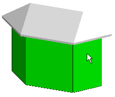
- Select Confirm.
- Select the main bay window roof slope.
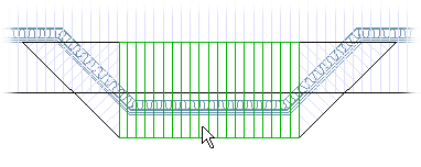
The program will add trusses to the main slope, and also to side slopes, if you selected the check box Side trusses in the Truss Parameters dialog box.