
Cut Projection Detail
This function is available in the Vertex G4 application.
You can create a detail view of the elements in a drawing.
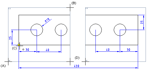
- The creation of a projection detail begins with a whole, finished projection, that is cut, for example, into two or several projection areas.
- A reference point is selected from the projection area, making it possible to use dimensioning between the projections. The borders of the projection area are not displayed in printouts.
- On the
 tab, in the Tools group, select Projection, and select
  Projection Detail.
 - In the Projection Detail dialog box, select
 Cut projection detail.
- Click the lower left corner of the of the detail magnification.
- Click the lower-left corner point (A).
- Click the upper-right corner point (B).
- Select the position of the reference point (0,0) in the projection area (C).
- Click the next projection area. You only need to click the position of the reference point in the first projection area.
- Select Confirm.
- Do either of the following:
- Click two points to specify the empty space (D) between the projection areas.
- Click the
 button and enter the distance between projection details as a numeric value (mm).
- Stop using the function by clicking the Cancel button in the dialog box.

Note:
- Set projection area limits either on or off.
- Set the projection area limits visible / off