
Create a Model Drawing
General
- When you create a model drawing, the drawing will inherit some of the model's archive data.
- The archive data of the model and drawing will not be cross-updated. A model can describe several products if the model has been designed with different configurations.
- A model can have several drawings. The number is unlimited.
- The label of the first drawing is the same as the label of the model by default.
- To the following drawings, a number code is added after the underscore.
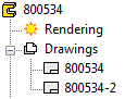
Create a New Drawing of the Model
- Open the part or assembly on the Vertex desktop, unless it is already on the desktop.
- If necessary, activate a certain configuration of a model, which you wish to create a new drawing.
- Start creating a new drawing:
- Double-click
 Drawings in the tree.
 - Move the cursor on Drawings in the tree, and select the context-sensitive function New Drawing.
- The program opens the dialog box New Drawing.
- Double-click
- Select the properties of the drawing in the New Drawing dialog box.
 New Drawing dialog box
- Accept or change the label. Recommendation: accept the label.
- Select the scale.
- You can change the scale of the drawing later.
- Select the sheet.
- You can also select : No sheet.
- If you select a sheet, you will see the projections you have selected placed on the sheet at the bottom of the dialog box. So you can change the scale or sheet already at this stage.
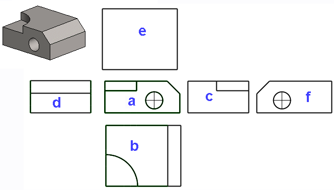
- Select the projections.

- a: front.
- b: top.
- c: left.
- d: right.
- e: bottom.
- f: back.
- You can also select a plane from the model to become the front projection when you click Select a.
- If you select the front projection, you can also select the top projection when you click Select b.
- If necessary, select the projection style.
- The default is European projection (EUR), which you can switch to American projection (USA)
- If necessary, select the projection style.
- If necessary, use the slide switch to adjust the distance between projections.
- Later, you can drag the projections further or closer together.
- You can also specify the distance between projections by using a distance constraint.
- If necessary, select another projection. (If no other projections are selected, the default is None.
- ISO, 45 Back Right.
- ISO, 45 Front Right.
- ISO, 135 Back Left.
- etc.
- If necessary, select the viewing direction from the model by clicking Viewing direction.
- You can then enter the angles of the viewing direction or click Select at model and
- click the plane from the model that is positioned perpendicular to the drawing plane in the projection.
- Perspective
- If necessary, select perspective projection.
- Exploded view
- Only available when creating an assembly drawing.
- Select the presentation.
- Wireframe (traditional mechanical drawing consisting of lines).
- Shading (quick method, but you cannot dimension the drawing).
- Shading+Wireframe.
- LightWorks shading. (Requires the Visualization add-on option).
- LightWorks shading+Wireframe. (Requires the Visualization add-on option).
- If you chose a drawing method other than Wireframe, you can choose the drawing resolution of the shaded drawing by clicking Advanced.
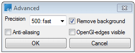
- Select on or off

 Exact silhouette lines.
- If the shape lines of the projection in the drawing are drawn incorrectly, edit the projection and change this selection.
- For more information, see the instructions Dialog Box: New Drawing and
- Silhouette Settings in the windows.xy File
- Also select on or off Also for spline surfaces.
- This is only available if you selected Exact silhouette lines.
- If the shape lines of the projection in the drawing are drawn incorrectly, edit the projection and change this selection.
- Select on or off Centerlines.
- The center lines are drawn for circles and cylinder surfaces, except for roundings and spherical surfaces.
- Select on or off Centerlines for pipe parts.
- If necessary, select centerline offset
- Absolute offset.
- Relative length.
- Enter the offset value if necessary
- Select on or off Hidden lines.
- Select on or off Auxiliary geometry.
- Select on or off Machining features.
- Select on or off Gravity center.
- Select how to draw tangential lines, or so-called apparent shape lines.
- Select OK.
- The program generates the drawing of the model.
- The program copies the model's archive data and presents the archive data
- Edit and fill in the archive data of the drawing, if necessary.
- Select OK.
- Save the drawing by using the function:
- File > Save or
- Press Ctrl+S or
- Select from the quick access toolbar:

An example of drawing projections
Note:
-
You can add a projection in a model drawing – an isometric projection, for example. Move the cursor in the model drawing window and select the context-sensitive function Projection.
-
You can edit the projection settings. Select a projection from the drawing and the Properties function.