
Show or Hide Geometry Constraints of a Sketch
General
- Geometric constraints are displayed as dimension constraint or graphical symbols between elements.
- The dimension constraint or symbol indicates that there is a geometric constraint between the elements.
- Other than the dimension constraints can be hidden and displayed again, if necessary.
- The size of the constraint symbols is determined by the sketch properties setting Sketch scale.
- We recommend to select Auto as the sketch scale.
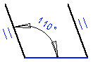
- The dimension constraints are always visible. The dimension constraint is highlighted in blue when the geometric constraint is in effect.
Show or hide the constraints
- Press the F9 key to toggle the visibility of the graphical symbols.
- Select the setting File >
 User Preferences > Drawings, Models on the View tab in the Common group
 Show constraints: The constraints are visible.
 Show constraints: The constraints are not visible.
Graphical Symbols of Constraints
| Meaning | Symbol |
| Center |  |
| Perpendicular |  |
| Equal distance |  |
| Equal radius |  |
| Concentric |  |
| Symmetrical |  |
| Tangential |  |
| Parallel |  |
| Direction |  |
| Coincident | There is no symbol for the constraint |
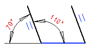
Overdefined, unsolved constraint is highlighted in red color.
Select a constraint to edit or delete
- Select the constraint either
- From the list of constraints or
- Select the symbol of the constraint in the graphics window.
 You can select a tangential constraint in the graphics window when you deselect Snap to Line on the tool strip.