
Edit Line Properties in a Model Drawing
General
- You can edit the properties of the lines visible in the model drawing per part or sub-assembly in the drawing, so that the changes are only visible in this drawing.
- You can also edit the drawing of the lines of a part or sub-assembly in the model, so that the changes are reflected in all drawings of the model.
Usage examples
- Lay-out planning, where new items can be highlighted and items to be dismantled can be faded "half-hidden".
- Representation of reference geometry surrounding a device.
- Visualization of the "contract limits" of a lay-out plan.
- Highlighting different lines (e.g. pipelines) with colors.
Change the line properties in a model drawing
- Open the model’s structure in the drawing's feature tree.
- Select a part, parts, sub-assembly, or sub-assemblies from the tree.
- Use the Ctrl key if you select more than one part or sub-assembly.
- Select the context-sensitive function Set Line Properties.
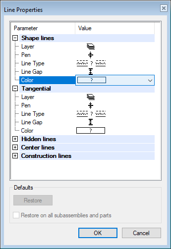
- The program opens the dialog box Line Properties.
- The program opens the dialog box Line Properties.
- Select the line type whose properties you want to edit.
- Shape lines.
- Tangential, or apparent shape lines.
- Hidden lines.
- Center lines.
- Construction lines, i.e. lines of auxiliary geometry, such as guide lines.
- Under the parameter you want to edit, select the preset button
 .
.- Layer
- Pen, i.e. line thickness (0.1mm .. 1.0mm).
- Line type.
- Line gap, i.e. the width of a two-dimensional line.
- Color.
- Select the property from the list.
- Confirm the line properties by clicking OK.
- The program updates drawings projections
Change the properties of lines in all drawings of the model.
 The properties set per drawing overwrite the line properties given in the model.
- Select a part, parts, sub-assembly, or sub-assemblies from the model’s feature tree.
- Use the Ctrl key if you select more than one part or sub-assembly.
- Select the context-sensitive function Set Line Properties.
- Continue as above steps 4... 7.
Reference Part Line Properties
- Parts of adjacent assemblies can be retrieved as reference parts for the subassembly drawing of an assembly.
- See: Display Reference Parts in Drawing Projections