
Tool Strip - General
General
-
The content of the tool strip is defined according to what kind of object is opened in the window.

- The Pin icon hides or pins the toolbar. When hidden, the tool strip is activated when the cursor is placed over it.
- The next icon moves the toolbar to either the right edge or the top edge of the working window.
- The point, line, and surface icons allow you to switch searches to elements.
- Green icons control the views of objects displayed on the screen.
- Views can also be saved.
- The view of objects can be changed to wireframe or shading.
- Auxiliary geometry can be shown and hidden (G).
- The 3D limits can be set or deleted.
- The predictive feature can be turned on and off.
- Coordinate systems can be set from the coordinate system icon.
- The working window is released or restored.
Projection change
- The projection change function can be used to change the projection of the model window relative to the model and the coordinate system.
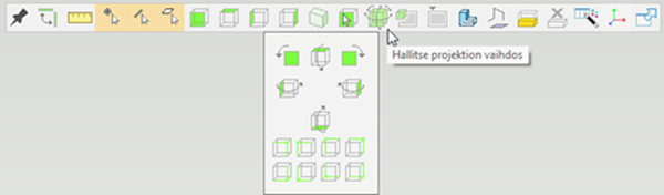
- Rotation in relation to the axis of the viewing direction of the display rotates the model 90 degrees in the direction of the arrow shown on the button. The left button rotates counter-clockwise and the right button rotates clockwise.
- When clicking on the left edge, the model rotates so that the edge in question moves towards the viewer.
- The isometric views from the top are shown with green highlights in the corners of the cube and describe which sides (or main directions) the isometric view is created with.
- The bottom icons can be used to select isometric views from below.
Note: The projection change feature is found in the toolbar, which allows you to open the key menu.