Geometric Constraints Visible
The geometric constraints are displayed as dimension constraints or graphical symbols between elements, in points, or between points and elements. The dimension constraint or symbol indicates that there is a geometric constraint between the elements.
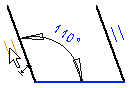
- The dimension constraints are always visible. The dimension constraint is highlighted in blue when the geometric constraint is in effect. The fixed line is also highlighted in blue.
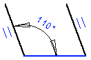
- Other geometric constraints, for example, such as Parallel constraint, is displayed as graphical a symbol.
The displayed symbol is highlighted in blue when the geometric constraint is in effect.
- Set constraints visible as follows:
Select
 >
>  Preferences >
  Drawings, Models.
Select View >
 Show Constraints.
Press the F9 key to toggle the visibility of the symbols.
Meaning Symbol Midpoint 
Perpendicular 
Equal distance 
Equal radius 
Concentric 
Symmetry 
Tangential 
Parallel 
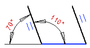
- In the drawing, unresolved constraints will be highlighted in red color. For example, if too many constraints are defined for the elements, the drawing is overdefined and the color of the constraint changes red.
In the image below, the other dimension constraint is extra. Compare to the figure above. You can fix the situation by deleting the extra constraint.
Note:
- If necessary, zoom the drawing in order to see the symbol.
- View elements related to a constraint, by selecting
 Delete constraint in a Drawing
 - Select a graphical constraint symbol by clicking it. You can delete a constraint by using the Delete function or pressing the Delete key.