
Add a Height Symbol
Architectural, Framer
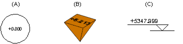
With this function, a height mark is added to a 2D drawing, a 3D model, a geometry derived from the model of a building opened from the drawing sheet (in an elevation, section or perspective drawing) or a wall panel drawing. A height mark may look like this, for example, in a floor plan (A), a model (B) or an opened geometry (C):
Height Symbol to an Elevation, Section or Perspective drawing
- Open the drawing sheet on which the view is.
- Open the view drawing from the sheet.
- Do either of the following:
- Right-click to open the context-sensitive menu, and select
 Add Height Symbol.
 - Select Modeling | Drafting |
 Details
 Add Height Symbol.
- Right-click to open the context-sensitive menu, and select
- Click the location of the height symbol

Note: The drawing file for the height symbol included in the basic program delivery is ../system/macros/system/hgtmark.elev.vxp.
Height Symbol to Floor Plan Drawing or Model
- Select Modeling | Drafting | Details Add Height Symbol.
- When you add a height symbol to the floor plan drawing, the value defined in the building coordinates and height data is displayed in a text box. If a horizontal structure has been added to the drawing, you can select the auxiliary function
 Height from floor from the right-click menu, and click the horizontal structure which defines the height value.
 - Click the location of the height symbol
Note: The drawing file for the height symbol included in the basic program delivery is ../system/macros/system/hgtmark.top.vxp and the model file ../system/macros/system/hgtmark.vxm.
Height Symbol to Wall Panel Drawing