
Creating Main Diagram
Creating of the main diagram is started by creating a drawing sheet basic drawing for the main diagram in the archives, to which (basic drawing) the whole main diagram is created as a single complex.
- The main diagram form is distributed to separate drawing sheets with the appropriate function, if necessary.
- All modifications of the main diagram is performed in the basic drawing. Also the updating of the output numbers will use the basic drawing of the main diagram for the search of numbering. Editing of the main diagram can be used functions of the create main diagram tool or tools of the basic graphics.
A pagination of the main diagram can be done from the basic drawing in two different ways:
- Method 1: The basic drawing is created on the form 0. Then the hub label must be in the drawing archives card. Forms to be paginated will be forms of the same drawing number started from the first form.
- Method 2: The basic drawings are created other than the form 0, even with the same drawing number, if necessary. In this case, it has to mark PKAAVIO in the drawing archives card, and the hub label in the form archives card of each basic drawing. The markings for the archives cards will be added in the field: Label defaults (=)
Depending on the basic form number, the create main diagram tool checks from the user archive markings, and if necessary, asks for the user to add the hub data in the database. Pagination requires that in the hub data is defined to which drawing number the pagination is derived. If the archives data is inadequate, the pagination is prevented.
Creating a Diagram Using the Editing Tool
The main diagram created with the help of the editing tool can be sorted out output number order before the pagination. For the first form of the paginated main diagram is imported a form, in which is the hub data.
The main diagram consists of outputs which are displayed with entities separated with dash-dot line when using the editing tool.
- Each output can consists of desired number of main diagram lines.
- A new output includes two lines by default.
- Each output can only include one output number.
The editing tool of the main diagram is used from the keyboard. Starting of the editing tool opens an own new editing window for the main diagram. The cursor is displayed in an active field, which points a line/column, to which the entered command is point out. The cursor can be moved with the Cursor keys and data can be edited/added with own commands. The editing tool is interrupted with the Esc key.
 Pagination is based on the drawing
structure created with the editing tool. Tools of basic graphics can be used to complement the
drawing without removing the structure.
Pagination is based on the drawing
structure created with the editing tool. Tools of basic graphics can be used to complement the
drawing without removing the structure.
- Select Building Application>
 Create Main Diagram.
 Keyboard Commands in Main Diagram
Design
Keyboard Commands in Main Diagram
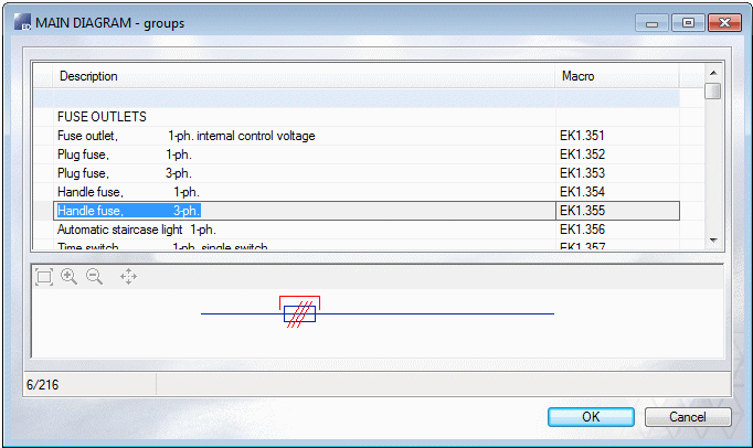
DesignAs an example, press A key. Select the Input and Output of the main diagram in the database view. You will see the selected in as an image in the bottom area.
 Note
Note
- The lower bar can be added or removed by selecting PK_KISKO or (remove -PK_KISKO), when
adding a group. When adding and removing the lower bar, an automatic stretch is done and
output number is moved to the right from under the lower bar.
The line entirely without a bar can be added by selecting the Add row function and entering 0 as a line number. The line symbol (PK_RIVI4) without a bar must be found from the symbol library.
- You can define the hub data using the function Edit Dboard Database.
- Before creating the main diagram, mark outputs into the layout drawing.