
3D Flattening
Sheet-Metal Design
General
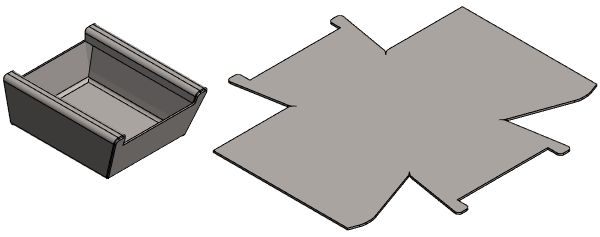
- The function flattens the model in the model window.
- Flattening will take into account the strain of the sheet in accordance with the calculation method selected.
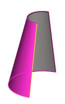
 If the face to be flattened is a ruled face, flattening will not take into account the strain of the sheet.
- 3D-flattening is necessary if, for reasons of manufacturing technology, the sheet is machined at the bends before the sheet is bent to its final shape.
- When trimming a corner, flattening in the 3D model is necessary. Trim a Corner.
- 3D-flattening is useful when positioning machined features, which are very difficult or impossible to model in a bent state.
- Avoid unnecessary flattening and rebending of the model, as these may disrupt the model's geometry and make it unusable.
- If the face to be flattened is a ruled face, rebending is not possible.
- Ruler surfaces include conical surface and conical spline surfaces.
- This means that you cannot add features (for example holes or forming features) to the flattened part and then rebend the part to the bent shape.
- If the flattening of a ruled face fails, you can try to make the tolerance value larger.
- Spline surfaces are flattened in relation to the so-called neutral axis starting from version 22.0.03.
- The bends done with older versions are created in accordance with the selected surface.
- If you want to update an old flatten drawing to a new one, the model's flatten configuration must be removed before updating the drawing.
Perform the flattening
- Select the ribbon bar function Sheet metal part | Tools |
 Unbend.
- The program highlights the largest surface of the part as a reference surface, along which others will be turned.
- The program prompts you to accept the surface or to click a new surface to flatten.
- Accept the selected surface or click a new surface.

- Accept the surface suggested by the program by selecting Confirm. (Confirm = V key, middle mouse button or the context-sensitive function
 OK.
OK. - Or click a new reference surface.
- The program opens the dialog box Bend Properties, if the stretch calculation method is
- BendTable.*
- K-Factor.
- The program skips the dialog box Bend Properties, if another stretch calculation method is chosen, for example
- DIN6935, FeAlCuZn, NEUTRAL, NOSTRETCH, etc.
- Accept the surface suggested by the program by selecting Confirm. (Confirm = V key, middle mouse button or the context-sensitive function
- If the sheet metal part to be 3D-flattened is formed by a cylinder surface (ruler surface), accept the proposed end or select another end.
- Accept the line suggested by the program by selecting Confirm. (Confirm = V key, middle mouse button or the context-sensitive function OK.
- Or click a line at the stationary end.
- Accept the line suggested by the program by selecting Confirm. (Confirm = V key, middle mouse button or the context-sensitive function
- If you have selected BendTable or K-Factor as the stretch calculation method, fill in the data in the Bend Properties dialog box.
- V-Opening. (If BendTable* is selected as the stretch calculation method.)
- Tool Radius (if BendTable* is selected as the stretch calculation method).
- K-Factor. (If K-Factor is selected as the stretch calculation method.)
- You can assign values to all bends at once, or you can select a bend from the list and assign individual values to it.
- Select OK.
Create flattening based on the selected surface
- Select the surface parallel to which you want the other surfaces of the part to turn.
- Select the context-sensitive function
 Unbend.
- Depending on the stretch calculation method, the program opens or skips the Bend Properties dialog box.
- Continue as above 3...4.
Note:
- The strain calculation method is a sheet metal part property which you can redefine by clicking selecting the part and the context-sensitive function
 Properties.
 - If you make changes to the sheet, you can rebend it by selecting the function
 Rebend.
 - You can add a flattened view to a drawing by selecting flattening as one of the projections of the drawing. Create a Flattening Drawing
- Every configuration of a sheet metal part can have its own flattening.