
Edit Flattening Lines
Sheet-Metal Design
With the keywords related to sheet metal's flattening, you can edit for example line properties. For example you can transfer only the flattening's border lines from a drawing to a DXF file for a laser cutter.
Default setting's keyword group Bend
Common parameters of the keyword group:
- Layer
- Line Width
- Line type
- Scale
- Color
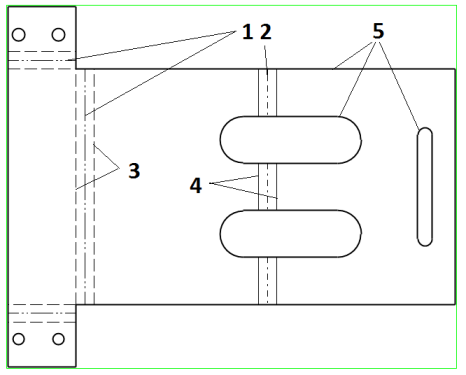
| Number in picture | Keyword | Effect range | Value |
| 5 | NormalGeomLine | Flattening's edge lines | |
| 1 | BendLine | Bending lines, if bending towards the viewer | |
| 2 | BendLine2 | Bending lines, if bending away from the viewer | |
| 3 | BendAreaLine | Bending area edge lines, if bending towards the viewer | If you want to hide the lines, set: Layer = 110 |
| 4 | BendAreaLine2 | Bending area edge lines, if bending away from the viewer | |
| DrawBendAreaLine | Drawing of bending area edge lines | 0 = Not displayed (default) 1 = Are displayed |
|
| FormingFeatDown | Shaping feature's geometry lines | Display the Forming Feature Side in a Flattened Drawing | |
| FormingFeatUp | Shaping feature's geometry lines | Display the Forming Feature Side in a Flattened Drawing |