
Example: Combined Library Feature
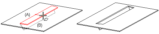
The software supplier's sheet-metal library features can be found in the Features/Sheet_metal directory of the feature library. As an example, view a combined library feature Lance1.vxm, that is both a cutout feature (A), in other words, it creates a hole in the sheet surface, and a boss feature (B), because it adds material to the sheet.
Model a part like Lance1.vxm as follows:
- Start creating a new part. Begin modeling with the part that adds material. Create a sketch and extrude it lengthwise. The sketch is highlighted with a yellow color in the extruded part (A). Define the length of the extrusion and a variable for it, for example B.
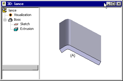
Figure 2: Sketch A has been extruded and a variable B has been assigned to its length. - Define the part as a sheet-metal part, because the feature is a sheet-forming feature. Select the part and select the context-sensitive function
 Properties and
  Sheet Metal in the Type section.
 - Draw a new sketch at the edges of the sheet (B) at both ends of the sheet to act as a cutout feature for the edges. Define extrusion through the part.
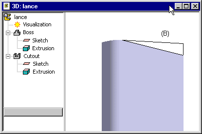
Figure 3: The bossing feature has now been modeled. Next, model the cutout feature. - Add a new sketch to the face of the sheet-metal part and draw the sketch (C). Extrude a boss and select

 Make Tool in the feature properties. Define the length of the extrusion as negative to position the bossing in the direction of the negative Z axis on the sheet. Define a negative variable -t for the length. The machining feature is highlighted in the model with red color.
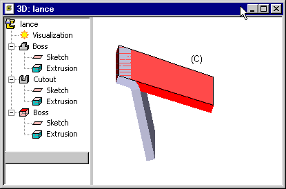
Figure 4: The model now contains a cutout feature and a boss feature that partially coincide. - Finally add a guide curve onto the machining feature to make it easy to position the handle.
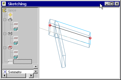
Figure 5: A guide curve makes it easier to position the handle. - Delete the old handle (that is the origin of the sketch), and define a new handle on a point on the guide curve. Note the unusual direction of the Z axis of the handle in connection with a sheet-forming library feature, Compare with a library feature that is only a cutout feature, where the direction of the Z axis of the handle coincides with the normal of the sheet face.
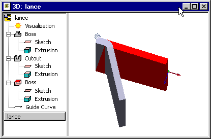
Figure 6: When you add the feature on a sheet, its Z axis will not be set coincident with the sheet face normal, but in the direction opposite to the sheet face normal. - Finally save the model to the feature library. Select Tool geometry first in the Choose tool execution order dialog box.