
Route a Pipeline
Piping Design
Model a pipeline by sketching the pipe routing. A pipeline is formed from pipe components, which comprise pipes and pipe parts. As an example, straight pipe and curve.
- Model a Pipeline along a guiding line.
- Add a pipeline by defining the route of the pipe's centerline by clicking points.
- The direction of a pipeline added in the vertical direction (Z axis) will be automatically fixed.
- A pipe part (elbow) will be automatically added between pipes in places where the pipeline's direction changes.
- Model the pipeline close to the actual dimensions. Refine the pipe lengths and their relative positions using geometric constraints.
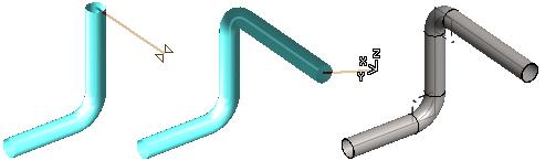
- Create a new assembly.
- Select from the following options.
- On the
 tab, in the Add group, select
  Add pipeline. (G4)
 - On the
 tab, in the Pipes group, select Add pipeline (G4 Plant).
- On the
- Select from the following options.
- Select from the
 Properties group Material, Pipe diameter, Wall thickness, and Bend radius. (G4)
 - Select in the Properties group Pipe class, Nominal size, Wall thickness, Pipe item, Curve item (G4 Plant).
- Select from the
- Select either of the following:
- Select
 Using elbows for the places where the pipeline's direction changes.
 - Select
 Using bending for the places where the pipeline's direction changes.
- Select
- Click the start point of the pipe's centerline.
- Enter the line position to be used.
- Define the sweep plane in one of the following ways:
- Select the sweep plane with a context-sensitive function, for example
 Horizontal (XY) plane, or press Shift+O.
The plane lock is enabled until you release it with the F key or select another lock.
- Sweep Plane Direction Based on Line
- Sweep Plane Based on a Planar Face
- Sweep Plane Based on Three Points
- Select the sweep plane with a context-sensitive function, for example
- Define the sweep direction in one of the following ways:
- Constrain the cursor into a ruler.
- Select the sweep direction with a context-sensitive function, for example X axis direction.
- Planar Face Normal as a Sweep Direction
- Line as a Sweep Direction
- Do either of the following:
- Enter a length for the pipe on the keyboard.
- Before clicking a point you can snap the cursor to a point or line on the model when the Snap function is selected.

To a point, line or face when the Snap function is selected.

- Click a pipeline point. Continue modeling the pipeline by clicking the next point. In the routing points, select bending radius of the curve on the tab Properties group field.
- When routing the line you can add a component by pressing the B key. Continue routing by confirming the component position by selecting Confirm.
- Undo the previous point by pressing Ctrl+Z , and click the point again. You can undo the added points of the same pipeline all the way to the starting point.
- Select Confirm.
Open from the Archives or from a Library
Modeling auxiliary functions - Mechanical Piping / G4 Plant
Note:
- Pressing the K key shows the directions of the coordinate axes at the cursor.
- The first pipe component added to an assembly is fixed in place, indicated by the lock symbol
 . The component's location will not change if you drag other components of the pipeline. The length of the fixed component will change unless it is defined with a dimension constraint. You can fix and release components using the F key.
- If you do not define the position or length of a pipe component accurately when it is modeled, it will be positioned in the assembly using geometric constraints.
- You can also model a pipeline by adding pipes and pipe parts from the component library.
- If you are routing a pipeline using bent pipes, the pipe sections of the pipeline form a single entity. The pipe sections are grouped into a kind of a subassembly within the assembly tree. Bent pipe sections are listed as single rows in the parts list.
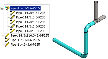 Note: You can view and print data of bent pipes for a pipeline made by bending.