
Set the Visibility of a Building Component in Drawing-Model Pairs
By default, the geometry of building components is shown in only one drawing-model pair: the one to which the building component has been added or moved. If necessary, you can set the components visible also in other drawing-model pairs. For example, you can show columns, beams and chimneys in both architectural and framing model. Similarly, you can show a grid or section symbols in the floor plans of desired floors.
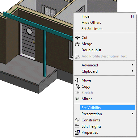
- Select one or more building components.
- Right-click to open the context-sensitive menu.
- Select Set Visibility.
The Select Drawing-Model Pairs dialog box opens. Drawing-model pairs are grouped by the floors of the building in the dialog box.
The drawing-model pair in which the original geometry of the component is, is greyed out. You cannot change the visibility of the building component in this drawing-model pair.
- Select the drawing-model pairs in which the geometry of the building component will be shown.
- Confirm by clicking OK.
Note:
- The customer-specific template building does not necessarily have a "Foundation, framing" drawing-model pair. However, the drawing-model pair is necessary if you wish to set the foundations visible in the framing model. Add the drawing-model pair, if necessary: Example: Framing Drawing-model Pair of Foundations.
- You can also use this function to set the visibility of objects in an imported IFC model. If 2D representation is selected for IFC objects, the 2D geometry of the object is also displayed in the drawing-model pairs where the object is set to be visible.