
Set the Default Frame Origin
You can use the default frame origin to help align frame structures on walls, floors, ceilings, and roofs. You can also use it to align the vertical cladding of a wall.
The default frame origin defines the location of the first part of the structures. This is the first stud on the walls, the first joist on the floor and ceiling structures, and the first truss or rafter on the roofs. The parts are distributed from the default origin base point in both directions according to the spacing of each structure.
- inside the selected area
- in the selected direction
- for the selected structure types
- on the selected floors
Set the default origin before adding parts to structures. Set the default frame origin as follows:
- Select Modeling | Panel |
 Wall >
  Set Default Frame Origin. The Default Frame Origin Properties dialog box opens.
 - In the dialog box, specify which directions and structure types are affected by default origin.
- Directions - Select either of the following:
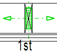
- Only set direction - For example the x axis direction:
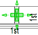
- Set and perpendicular - For example the x axis direction and y axis direction:
- Only set direction - For example the x axis direction:
- Affected structures - Select the structure types that will be affected by the default origin.
- Affected structural layers - Select the layers that will be affected by the default origin. For now, only the exterior wall cladding layer Vertical cladding is available. When a layer is selected, the default frame origin base point is also the starting point of the vertical cladding. The alignment affects all vertical cladding layers that match the direction and area of the default frame origin.
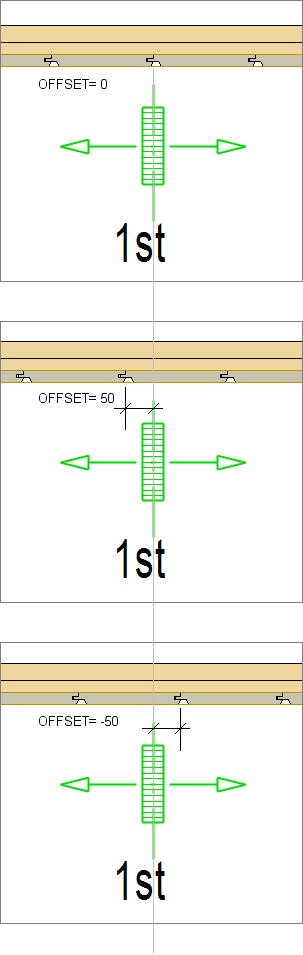
In the framing tool of the siding layer, it is possible to set an offset for the start of the cladding relative to the default frame origin base point. A positive value moves the start in the direction of the male tongue. See Framing Tools: Cladding.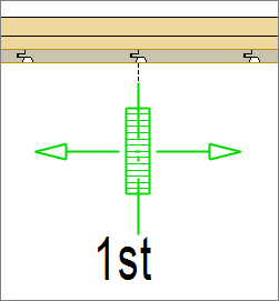
 Note: The default frame origin does not affect cladding layers where the starting edge of the installation direction is defined using an edge detail. See Edit the Edge Detail of a Cladding.
 - Set Visibility - Display the base point in those drawing-model pairs that you want the default origin to affect. Drawing-model pairs are grouped by the floors of the building in the dialog box. The drawing-model pair in which the original geometry of the base point is, is greyed out. You cannot change the visibility in this drawing-model pair. Select the other drawing-model pairs in which the geometry of the base point will be shown.
- Directions - Select either of the following:
- Define the effect area by clicking the points of the line that limits the area. You can easily determine a rectangular area by selecting the end points of the diagonal.
- Select Confirm.
- Click the location of the base point.
- Click the direction of effect. Lock the cursor, and click a point in the desired direction from the base point.
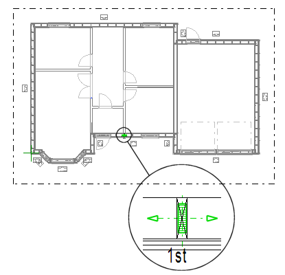
The program adds a symbol to the base point and marks the boundaries of the selected target area.
Add parts to structures after setting the default frame origin.