
Procedure of Creating Panel Breaks
Framer
- Select Classic Wall Framing | Wall Panelizing |
 Generate Panels.
 - You can limit the number of walls selected by choosing a basic wall type. Select a type
from the additional menu.
 Select Exterior
Wall - When the function is selected, you can select exterior walls.
Select Exterior
Wall - When the function is selected, you can select exterior walls. Select Interior
Wall - When the function is selected, you can select interior walls.
Select Interior
Wall - When the function is selected, you can select interior walls. Select All of Same
Type - When the function is selected, you can select all walls of the same
type by clicking one wall of the desired type. The walls are of the same type when they
have the same parameters.
Select All of Same
Type - When the function is selected, you can select all walls of the same
type by clicking one wall of the desired type. The walls are of the same type when they
have the same parameters.  Either
of the basic wall types must be selected at the same time.
Either
of the basic wall types must be selected at the same time.
- Select the wall or walls. If you selected the function Select All of Same
Type, click one wall of the desired type. All the other walls of the same type
become selected at once.
- Select Confirm.
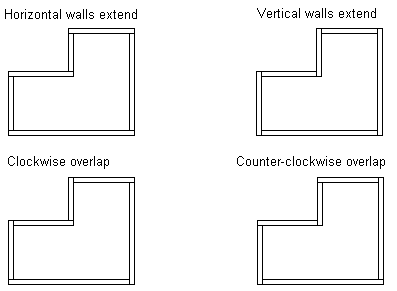
- Select one of the following alternatives as the corner overlap:
- Horizontal Walls Extended
- Clockwise
- Counterclockwise
- Vertical Walls Extended
Horizontal walls are the walls parallel to the x-axis in the floor plan drawing, and vertical walls are the walls parallel to the y-axis. The break points of panels that depend on the corner overlap type are displayed below.
 The corner overlap selected does
not apply to the corners where the framing lines of the walls have been trimmed so that
the walls are cut at the corner.
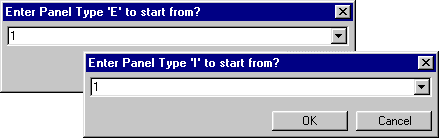
The corner overlap selected does
not apply to the corners where the framing lines of the walls have been trimmed so that
the walls are cut at the corner. - Define the first panel numbers of the various wall types. The wall type label has been
determined in the wall attributes. Type the numbers in the text boxes that open one after
another.
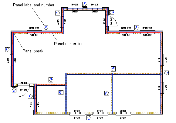
The program will mark on the floor plan drawing the center lines and break points of panels, the labels and numbers of wall panels, and the labels and sizes of openings (windows or doors).
If a panel exceeds the maximum
height defined in the setup file ../custom/details or ../system/details folder, the
program will notify about this in a message box. If you do not accept the panel height,
the panel cannot be generated. You need to edit the panel height and then regenerate the
panel. - Select whether you wish to add backers at panel joints. When you click
Yes in the message box, the program will add backer macros at the T
joints of walls selected for panelizing and walls connecting them on the floor plan drawing.
If you have added the backers previously and the floor plan drawing has not changed since
then, you can click No. If you choose to add the backers, the next
message box prompts you to select whether you wish to replace existing backers if there are
any in the floor plan drawing.
- By clicking No in the message box, you can add backers only where there are not yet any backers.
- By clicking Yes, the program removes the old backer, if a new backer is added at the same location. If there are no existing backers, it does not matter which option you select.
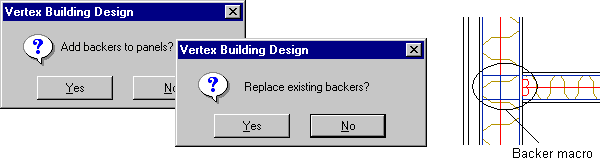 The backer detail (its cross
section size and location) is defined in the building parameters.
The backer detail (its cross
section size and location) is defined in the building parameters. - Save the building by selecting File >
 Save Building. At
this point, all the panel data is saved in the panel attributes.
Save Building. At
this point, all the panel data is saved in the panel attributes.
Below is an example of a floor plan drawing after generating the panel breaks.
- If necessary, you can also add backers after generating the panel breaks by using the Adding a Backer Macro to the Floor Plan Drawing function.