
Framing Tools: Cladding
Framer
Tool for the cladding or cover layer (COVER) of a wall panel, horizontal structure or horizontal structure panel. Select Tool from the list. The parameters are set according to the selected tool. If necessary, edit the parameters in the dialog box.
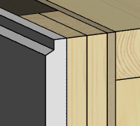
Siding
- Description
- Description text for the tool.
- Cross section
- Select the cross section of the boards with the Select button. Select the profile library and cross section in the Piece Properties dialog box.
- Spacing
- Enter the board spacing (S) in the field.

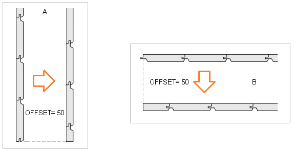
- Offset
- The installation of the cladding starts either from the default edge (the bottom edge of the layer for horizontal cladding, the left edge of the layer when viewed from the outside for vertical cladding) or another alignment method may have been defined for the cladding. See Cladding Alignment.
- Position angle
- The default position angle, which depends on the profile's cross section, is defined in the cladding library and does not usually need to be changed. If the cross section is placed in the wrong position in the cladding, determine how much the cross section needs to be rotated and add the angle to the default position angle.
- Direction angle
- Defines the direction of the boarding.
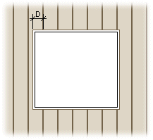
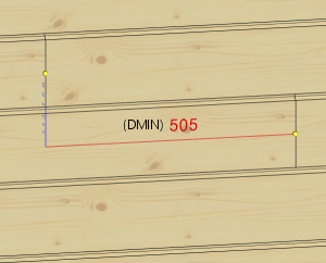
- Max. notch
- Enter the maximum size of a notch (D) made to a board next to an opening. If the notch is larger, the board will be cut at the opening.
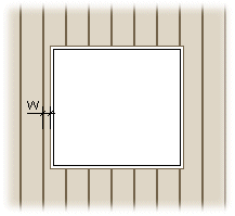
- Minimum width
- Enter the minimum width of a board (W) next to an opening. If the width is smaller, the board will be cut at the opening.
- Cut top board
- The property is relevant in a situation where the tongue of the top board of the horizontal cladding or part of it extends above the frame layer.
- When the property is not selected, the board is not cut if only the tongue or part of it extends above the frame layer. If the rest of the board also extends above the frame layer, the board is cut.
- When the property is selected, the board is always cut.
- When the property is not selected, the board is not cut if only the tongue or part of it extends above the frame layer. If the rest of the board also extends above the frame layer, the board is cut.
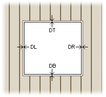
- Opening offsets
- Enter the distances of the boards from the opening edges in this field.
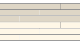
Automatic cut
- Automatic cut
- You can select an automatic cut for the siding boards in the cladding tool. The boards will be cut at battens. You can stagger the cut-off points on different board courses by entering the number of overlapping courses in the field Overlapping rows.
-
Overlapping rows = 2 Overlapping rows = 3 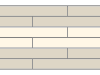
Mount
- Mount
- Select the mounting method of the cladding boards from the menu. All boards added with the tool will receive the same mounting method.
- Loose part - A part to be mounted at the building site.
- Mount manually - A part to be manually placed and mounted in the factory.
- Manually placed - A part to be manually placed but automatically mounted in the factory. You can use this mounting method for parts that the production line cannot automatically position due to the size or shape of the part, but over which the nailing and glue lines must continue.