
Move Faces
Advanced Face Modeling Package
General
- You can use face moving to stretch or shorten a part so that adjacent faces continue maintaining their direction.
- Use the function to stretch a part model when the part does not have a history that could otherwise be modified by editing.
- Suitable for stretching parts imported from other CAD systems.
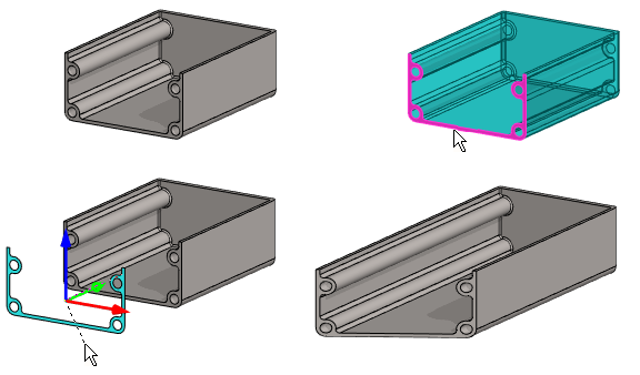
Move Faces
- Select the ribbon bar function Part | Faces |
 Move Faces or
- Import | Faces | Move Faces.
- Import | Faces |
- Select one or more faces.
- Select Confirm (Confirm = V key, middle mouse button or the context-sensitive function
 OK).
OK).- The program marks the faces to be moved in the model with red and
- opens the dialog box Move Face in which the faces to be moved are listed.
- Edit the set of faces, if necessary.
- Add.
- Change.
- Delete.
- Select OK.
- The program frees the faces to be moved to slide in the direction of the normal of the last selected face and
- Opens another dialog box Move Face in which you can enter a movement and angle.
 You can free or change the locking directions with the shortcut keys U, I or O.
- Define the new location of the face in the Move Face data dialog box.
- Click the new location for the face or
- The program fills in the values of the clicked movement in the dialog box.
- enter the values for the movement and angle in the dialog box.
- Distance in X ,Y and Z direction.
- Rotation angle around X, Y and Z axis.
- Formula, if you want to control the movement or angle with a dimension table.
- Click the new location for the face or
- Click Apply to see what the part will look like with the values you enter.
- Edit the data in the dialog box, if necessary.
- Select OK.
- The function stretches the faces adjacent to the moving faces, but their direction is maintained.
- If you did not select enough faces or entered "wrong values", no stretching will occur.
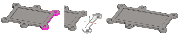
Moving selected faces
- Select one or more faces in a part model.
- Hold down the Ctrl key if you select more than one face.
- If you select more than one face, first select the face in the normal direction of which you want to move the faces by default.
- Select the context-sensitive function
 Faces>
  Move. If you selected more than one face, select the function for the face that you selected last.
 - Continue as above, steps 4...7.
Example 1:
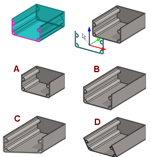
- A: X distance = 40.
- B: X distance = -40.
- C: Z rotation = 30
- D: X rotation = 30.
Example 2:
- The face is moved and rotated.
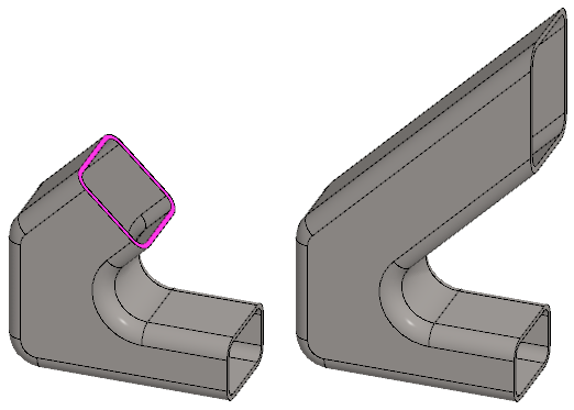
Example 3:
The cutting face of a toroid is moved
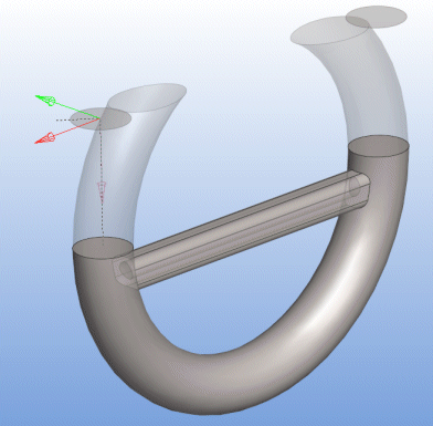
- The shape of the toroid is retained, but it is cut from a new location.