
MBD
General
- MBD markings can be added to a 3D model. MBD, or model-based definition, is widely used in Vertex G4.
- The basic idea of MBD is to move to a model without drawings.
Model-based product definition
- You can add boxed TED dimensions, or enter tolerances for the dimensions you want according to normal tolerance systems. In 3D, you can use length, angular, and diameter dimensions.
- Geometric tolerances, basic elements, limited basic elements, and basic element systems are available to you in 3D.
- Feature Data creates an MBD note type markup with #FEATURE# as text. The #FEATURE# text is replaced with the details of the feature associated with the element to which the markup is fixed. During editing, the dialog box preview field, or if no feature data is found for the selected element, “???” is displayed.
- Surface roughness symbols are placed in the same way as other MBD markings. It is also possible to place the general surface symbol on its own level.
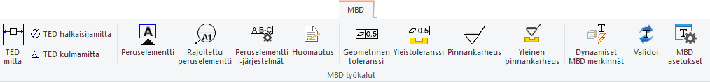
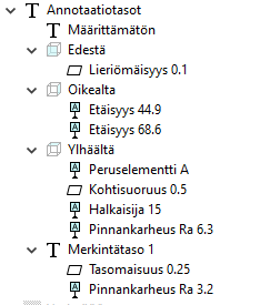
- Annotation views are designed to help manage markup visibility. They are a new concept in the assembly tree. The annotation levels describe the main directions in which markings can be placed. Changing the marking to another annotation level is done by dragging it to a new branch in the tree. Right-click the Annotations heading to display a menu from which you can choose what is currently visible. There is also a dynamic annotation mode in which only the markings visible in the viewing direction are displayed when you rotate the model.
Note: When creating a drawing, a function is used that adds the MBD markings to the model drawing. In this case, the user is left with the task of placing the markings in the drawing.