
Import 3D Model as a Drawing into 2D Window
Add a 3D model as an image to the 2D window. The image is not a model projection or a reference drawing.
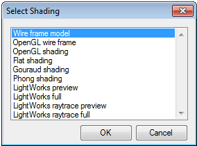
Select a drawing method for the model view: wire frame model, shaded model or a rendered model.
- When adding a wire frame model view, select an auxiliary positioning function, if necessary.
- When adding a shaded or a rendered model view, you can change its size before selection a position.
Note:
 The property is not used in the G4 ED application.
- Before selecting the function, confirm the working window is not in the Extend state. Set windows in the way off, you can point the desired 3D window.
- For example, smaller the size of the window, or overlap windows. After then select function. For example, split windows vertical before selecting the function.
Add a 3D model as an image to the 2D window as follows:
Importing a 3D View in the 2D Window
- On the
 tab, in the Tools group, click Projection, and select
  Import View from the Model.
 - Select the 3D window where the model is.
- Select the location points, and position the model image in the 2D drawing.
- Select the shading method. LightWorks is an option.
- Select OK.
- Based on the selected shading method, do one of the following:
- Click the
 button and enter a factor, which scales the image to the desired size.
 - Click the
 button and enter scaling factors in X and Y direction, separated by a comma (,).
 - Define the number Bit/pixel and raster (image) size in relation to the window size.
- Click the
- Click a new location for the raster.
- Select Confirm.
Import 3D View and Attribute Data to 2D Window
Vertex G4 Plant Design: For example, the attribute data of a pipe line carries over to the view elements in the 2D drawing.
- Activate a drawing window.
- On the tab, in the Tools group, click Projection, and select Import View from the Model.
- Select the 3D window where the model is.
- Select the reference point according to which the model is to be positioned in the 2D drawing.
- Continue as instructed above.