
G4 Plant Design
Piping Design / Isogen Isometrics
 Plant and Piping Design
Line Modeling
Lines are modeled in the assembly model. The Pipe Assembly property is set as the property of the assembly by default, if you add an assembly using the piping design function  Create New Assembly.
Possible line alternatives include:
Depending on the extent of the model, the assembly model may contain several lines in addition to other geometry. Possible line alternatives:
- Main line
- Branch line
The assembly tree contents are easier to manage if the main line and branch line are modeled separately. The assembly structure will also be easier to view.
- Individual pipe assemblies can be easily selected from the assembly tree.
- Components belonging to a pipe assembly can be easily displayed in the assembly tree and working window.
- Assembly tree functions are easy to target to a pipe assembly. For example, hiding or replacing a pipe assembly.
Example - Line Modeling
Draft a route for a pipeline.
- Add a pipeline by defining the route of the pipe's center line by clicking points.
- The direction of a pipeline added in the vertical direction (Z axis) will be automatically fixed.
- A pipe part (elbow) will be automatically added between pipes in places where the pipeline's direction changes.
- Model the pipeline close to the actual dimensions. Refine the pipe lengths and their relative positions using geometric constraints.
 Position Pipe Components Using Constraints
- If you are routing a pipeline using bent pipes, the pipe sections of the pipeline form a single entity. The pipe sections are grouped into a kind of a subassembly within the assembly tree. Bent pipe sections are listed as single rows in the parts list.
You can continue routing the pipeline from a pipe component.
- Continue the pipeline either as a continuous or jointed pipe.
- Continue the pipeline from a component.
- Continue the pipeline with a set-on.
- Continue the pipeline with a branch component.
- Route automatically.
A pipeline can end at the following:
- The end of the pipe
- A pipe component
- A branch component
- A set-on
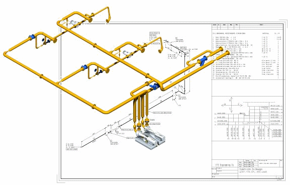
Isometrics
The finished pipeline includes all of the design data required for the generation of parts lists and drawings.
The isometric drawings of the pipelines are generated, including dimensions and parts lists.
Supports, Insulation and Profiles
Adding Insulation with an Insulation Table
Stairs, Maintenance Platforms
Collision Detection