
Degrees of Freedom
Define the allowed degrees of freedom
Vertex G4: Software's tip text informs the degrees of freedom, i.e. whether the part is for example sufficiently constrained or underconstrained.
Vertex G4Plant and G4: You can see from the symbols in the assembly tree if the part/subassembly is locked, fully constrained, underconstrained (-) or overconstrained (+).
 Assembly Tree Symbols and Conventions
Allowed degree of freedom means free movement in the degree of freedom's direction. For example, a bolt rotates in a hole or a slider moves parallel to a groove.
You can use the degrees of freedom of the library components to allow movement in the direction of the X, Y, or Z axes, and rotation around the coordinate axes in the kinematics viewing of the assembly. You can allow completely free movement or limit it to a certain range.
When you add a library component to an assembly, it is fixed to the assembly with a link referred to as Degrees of Freedom. The link will be displayed in the assembly tree as a geometric constraint affecting the part. The library component will not move in the assembly (default) unless degrees of freedom are defined for it.
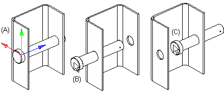
The handle of the library component displays the coordinate axes (A), its colors representing the X axis (red), the Y axis (green), and the Z axis (blue). Allow movement in the direction of the Z axis. When the component is dragged (B) (C), it will only move in the direction of the Z axis.
Define the degrees of freedom for the movement of a component as follows:
- Select a library component from the assembly tree.
- Select the Degrees of Freedom constraint and the Edit function. The handle of the component displays the coordinate axes, its colors representing the X axis (red), the Y axis (green), and the Z axis (blue).
- Fill in the data in the dialog box.
- The value of the centermost field is 0 (default value). It is the handle of the component, and a different value can be specified for it when it is not possible to point the exact location of the component directly from the assembly.
- Select the
 Oftset, when you allow the component transfer in the direction of the X-, Y- tai Z-axis. The other two fields of the dialog box become active. Fill in values limiting the movement or leave the fields empty to allow full freedom for movement.
 - Select the Torsion checkbox if you want to allow the component to have torsion in relation to the X, Y or Z axes. Define the rotation using the right-hand rule. The thumb will point in the direction of the axis, and the fingers in the fist will determine the direction of positive rotation. If necessary, fill in angle values limiting the torsion.
- Click OK.
- In the Piping Design (Option), the degrees of freedom will be defined for the constraint Handle linkage of the pipe component in the same way as for the constraint Degrees of Freedom.
- Software's tip text informs the degrees of freedom, i.e. whether the part is for example sufficiently constrained or underdetermined. Allowed degree of freedom means free movement in the degree of freedom's direction.