
Assembly Tree Symbols and Conventions
See also Feature Tree Symbols and Conventions.
Note
- In case of a large assembly, collapse the assembly tree by pressing Shift+Arrow right.
| Symbol | Meaning |
 |
Assembly |
 |
Normal part |
 |
Sheet-Metal Part |
 |
Profile Part |
 |
Piping component |
 |
Part Pattern |
    |
Flow model |
    |
A part or an assembly to which an item is attached (Flow link). |
 |
An item without geometry (Flow link). Geometry exists. Geometry exists, but it has to be displayed separately. |
 |
An item without geometry (Flow link). Geometry is missing. Geometry can be added to the item. |
 |
A link part of an assembly, associated with the original model. Suffix .L in the part label. |
 |
A local part of an assembly. |
 |
The part has an external reference. The highlight color is blue. |
    |
The part has been fixed (locked) in place. The calculation of the model's constraints is easier. The fixed part will remain stationary during kinematics viewing. |
 |
The subassembly has been fixed (locked) in place. |
 |
The part is an assembly-machining part. |
 |
The part is not completely constrained in the assembly, for example, geometric constraints are missing. This is not necessarily an error, but it is up to the user to decide when geometric constraints need to be added to the part. |
|
The part is defined in the assembly. |
 |
The part is overdefined in the assembly. |
 |
A constraint defined between parts of the assembly is impossible (unsolved). An element connected to the constraint (a point, line or face) is missing from the geometry of an assembly. The missing element is displayed in the model, if you click the constraint in the assembly tree. |
 |
The constraint between parts in an assembly is disabled. |
 |
The constraint definition connected to the SmartSnap component in the assembly is insufficient. A corresponding element connected to the constraint (a point, line or face) is missing from the geometry of an assembly. |
 |
The subassembly is not completely constrained (-) in the assembly, for example, geometric constraints are missing. |
 |
The subassembly is overdefined (+) in the assembly. |
| d.o.f 12/12 | When you select an assembly label (main level), the title of the tree's bottom frame contains information about the definition of the parts. The unfixed part has 6 degrees of freedom, 3 offset and 3 rotation. If two parts are located so that the parts can't move, the numbers are equal 12/12. If the other part is overdefined or underdefined, the latter number differs from the first one. The fixed part will be ignored. If all parts are fixed, the numbers are d.o.f 0/0. |
 |
The part has been hidden from the assembly model view. The part can be restored using an assembly tree function. |
 |
The subassembly has been hidden from the assembly. The parts belonging to the subassembly are also displayed grayed out. The subassembly can be restored using an assembly tree function. |
 |
The original model is replaced by the part's light model. This makes the model lighter to handle. The part can be restored using an assembly tree function. |
 |
The original model is replaced by the light model of the subassembly. This makes the model lighter to handle. The subassembly can be restored using an assembly tree function. |
 |
A lightweight model is being edited. |
 |
A mirrored part/subassembly. |

 |
A link part of an assembly, machined with an assembly feature. Suffix LM in the part label. A local part of an assembly, machined with an assembly feature. Suffix .M in the part label. |
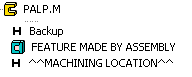 |
When the assembly is machined, the following symbols and features are displayed in the machined part's history, if the part has been imported to Vertex. The Backup means the history phase, in which the part is reversed to before machining, when the machining features are re-executed. A part can be machined using more than one machining feature. Each machining feature is displayed as a feature in the history with the convention Feature made by assembly. |
 |
The part or subassembly has a comment. |