
Define a Reference Grid
Plant
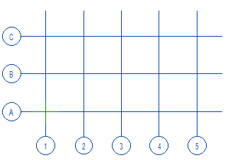
- On the Assembly tab, select the function
 Define reference grid. The Reference grid properties dialog box opens.
 - Select the reference grid properties in the dialog box.
- You can preview the reference grid by clicking Apply.
- Confirm adding or editing the reference grid by clicking OK.
By default, the reference grid is added to the origin point of the model. To click the location of the reference grid, do the following:
- First, select the reference grid properties in the dialog box.
- Select the Location tab and select Click.
- Click the location of the lower left corner of the reference grid and the direction of the horizontal grid lines.
- You can preview the reference grid by clicking Apply.
- Confirm adding or editing the reference grid by clicking OK.
Visibility of reference grids in drawings
When creating a completely new drawing, adding a new projection, or editing an existing projection, you can choose whether to turn the reference grid drawing on or off. If reference grids are drawn, in addition to grid lines, labels are drawn in 2D projections.
Note: The lines of reference grids are not ordinary guide curves, but lines of their own type. Therefore, the “Auxiliary geometry” setting of the projection no longer affects the drawing of these lines.
Note: The annotation functions of the reference grids found on the drawing tool strip are primarily intended for the annotation of old type reference grids, created before version 31, because the labels for these were not automatically drawn in the projections of the drawing.