
Reference Grid Properties
Plant
Select Assembly |  Define reference grid to add a reference grid. The Reference grid properties dialog box opens.
Shape
- Horizontal
- Select the properties of the horizontal lines.
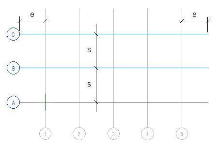
- Number of lines - Enter the number of horizontal lines.
- Spacing - Enter the line spacing in millimeters
- Line extension - Enter the length of the line extension (e) outside the grid in millimeters
- Labeling system - Select the line labeling system from the list.
- ABC
- 123
- 1. Label - Enter the label of the first line according to the selected labeling system.
- Label direction - Select the direction of the line label from the list.
- Horizontal
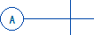
- Vertical
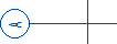
- Global horizontal

- Horizontal
- Label location - Select the location of the label on the line.
- Start
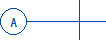
- End
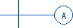
- Both

- Start
- Vertical
- Select the properties of the vertical lines.
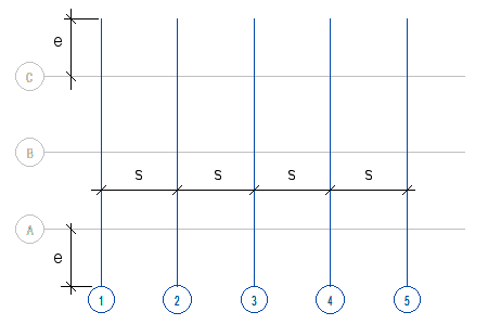
- Number of lines - Enter the number of vertical lines.
- Spacing - Enter the line spacing in (s) millimeters.
- Line extension - Enter the length of the line extension (e) outside the grid in millimeters.
- Labeling system - Select the line labeling system from the list.
- ABC
- 123
- 1. Label - Enter the label of the first line according to the selected labeling system.
- Label direction - Select the direction of the line label from the list.
- Horizontal
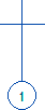
- Vertical
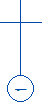
- Global horizontal

- Horizontal
- Label location - Select the location of the label on the line.
- Start
- End
- Both

- Start
Location
- Origin
- By default, the reference grid is added to the origin point. If necessary, you can enter the coordinates of the grid reference point in the X, Y, and Z fields. To click the position of the reference point, select Click.
- Rotation
- If necessary, enter the rotation of the reference grid in the xy plane in degrees. A positive value rotates counter-clockwise, a negative value rotates clockwise.
- Click
- To click the location and rotation of the reference grid in a drawing or model, select Click. Click the location of the lower left corner of the reference grid and the direction of the horizontal grid lines.
Plot
- Lines
- Select the line drawing properties Line type, Line width, Scale, and Color. To restore the default system properties, click Default. The default properties are set in the system settings with the line name GRID.LINE.
- Labels
- Enter the Height of the line labels and select the Color. To restore the default system properties, click Default. The default properties are set in the system settings with the text name GRID.LABEL.