
Material Layer
Edit the properties of the selected layer in the database view.
Tab: Material
- Type
- Select one of the following:
- Index
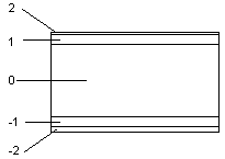
- Running number of the structural layer. The running number of the basic layer of the structure is 0. The layers below the basic layer are numbered with negative numbers starting from one, and the layers above the basic layer respectively with positive numbers, for example:
- Material
- Change the layer material by clicking the Select button. The function opens a new database view.
- Thickness
- The thickness of a layer is defined by the selected material. If necessary, you can type the desired value in the text field. If the thickness of the structure depends on a parameter, you can calculate it by clicking the Calculate button.
- Overlap Horizontal, Overlap Vertical
- This property sets the layer edges to extend beyond the edges of the basic volume. Enter the overlap value in the text field.
- U Value
- The U-value is used in the energy calculations.
 Indicative U
values have been determined for the building components in the structure libraries
included in the basic software delivery. The U value must be determined for the basic
layer of a volume.
Indicative U
values have been determined for the building components in the structure libraries
included in the basic software delivery. The U value must be determined for the basic
layer of a volume. - Display in 2D
- When this check box is selected, the edge line of the layer is presented in the floor plan.
- Edge Follows Parent Edge
- When this check box is selected, the edge of the layer follows the edge of the basic volume in the detailed presentation of the building's 3D model. This property is significant, for example, in roof structures. When the edge of a layer has been defined to follow the edge of a basic volume, the layers positioned above the basic volume conform to the selected eave shape.
Tab: Geometry
- Surface Prop.
- Defines the surface properties in the model. Select and edit the properties by clicking the View button. Select the surface material in the LightWorks Material Mapping database view.
- Hatch Properties
- Defines the hatch properties in the drawing. Select and edit the properties by clicking the Edit button. Select the properties in the Hatch Geometric Properties dialog box.
- 2D Line Props
- Defines the line properties in the drawing. Select and edit the properties by clicking the Edit button. Select the properties in the Line Geometric Properties dialog box.
- 3D Line Props
- Defines the line properties in the model. Select and edit the properties by clicking the Edit button. Select the properties in the Line Geometric Properties dialog box.
- Cross Section
- Defines the layer's cross section hatch which will be added in the vertical cross section created from the building's 3D model. Select and edit the properties by clicking the Edit button. Select the properties in the Hatch Geometric Properties dialog box.
- Texture File
- A texture file can be either a drawing or a model file.
- Texture Side
- Defines the surface of the layer to be textured. Select either of the following from the list:
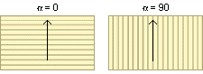
- Texture Dir in Slope
- Defines the direction of the texture hatch on a slope. Select either of the following:
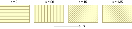
- Texture Angle in XY-plane
- Defines the direction of the texture hatch in a non-sloping structure. Select the angle from the list, or type a value in the text field. The angle is defined in relation to the x axis.
- Display Hatches as Lines
- When this property is selected, the hatch of the layer is exploded to lines. This enables you to snap to the line points.
- If the hatch is dense, a lot of
lines are created. This may make the model slower to handle.
 Note
Note
- The texture is only displayed in the model after you have selected the following
representation for the structure:
- Select the accurate representation for the structure by using the context-sensitive menu function Presentation > Accurate.
- Select the detailed representation of structural layers by using the function Expand Layers.