
The Component Change Dialog Box
Component Change
Define the component change rules in the dialog box.
Change operation
- New
Select a change operation to be edited from the list or create a new change operation by clicking the New button. Enter a name for the new change operation in the text field.
Define the tasks to be performed during the change operation in one or more of the following screens:
- What to change - Define the search criteria for the component
to be changed.
 What to change
 - Change to - Define the component to which the change is made,
or the component parameters that will be modified. If you wish to delete the component,
select the alternative NONE.
Change to
- Location - Define the location to which the component is moved.
Location
- Reference point - Select a reference point which will remain in
place when the component's size is changed.
Reference point
- What to change - Define the search criteria for the component
to be changed.
- Apply
Set the change operation to active by ticking the Active checkbox. The change operation set to active can be selected from the list in the Change Components function. If the building model includes options, the change operation set to active will be performed during option solving, if the option conditions are realized. If you wish to remove a change operation from use, select the operation from the list and clear the Active checkbox.
- Delete
You can delete a selected change operation from the list by clicking the Delete button.
What to change
Define the search criteria for the component to be changed.
- Object type
Select the type of the components to be changed from the list. If you wish to change all the components of the selected type, it is not necessary to define the search criteria presented below.
- Search criteria
The component search criteria is formed of a parameter and its comparison value, for example:
PARAM1 = 100
PARAM1 is the parameter
= is the comparison operator sign
100 is the parameter's comparison value
The comparison operator may be one of the following:
= Equal to <> Not equal to There can be several parameters, allowing you to use two logical operators in the definition of the search criteria: and or or.
- and - The component will be changed if both the comparison conditions are true.
- or - The component will be changed if either of the comparison conditions is true.
For example: USE = "ROOF" and PARAM2 <> 0
If the comparison value is a text, it will be displayed inside quotes.
Define the search criteria as follows:
- Click the Select button. The Available parameters database view
opens. The view presents the available parameters for components of the selected object
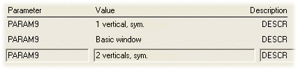
type. All values used in the building model are displayed for each parameter, which
means that the same parameter may appear on several rows. For example, a window
description text PARAM9:
- Move the cursor onto the desired row with the arrow keys and click the OK button to accept the selection.
- If necessary, edit the comparison operator in the Search criteria field.
- If you wish to use more than one parameter in the search criteria, you must first select either of the logical operators: and or or.
-
Select a second parameter and its value with the Select button etc.
- Classification Search Criteria
You can also search for a component on the grounds of the classification. The classification search criteria is formed of the classification's type and name, for example:
COMP_USE = "TERRACE"
COMP_USE is the classification type
= is the comparison operator sign
TERRACE is the classification
The comparison operator may be one of the following:
= Equal to <> Not equal to There can be several types, allowing you to use two logical operators in the definition of the search criteria: and or or.
The same classification type can appear several times in the search criteria and receive different values, for example:
COMP_USE = "U1" or COMP_USE = "U2"
The classification is displayed in inside quotes. If necessary, you can replace part of the text with the wildcard characters question mark (?) or asterisk (*). The question mark stands for a single character, and the asterisk stands for any combination of characters. For example, COMP_USE = "TER*".
Define the classification search criteria as follows:
- Click the Select button.
- You can select a classification from either the classification database (d_USE) or the classification list tree defined in the DesignStream system (the DesignStream Interface add-on feature).
- If necessary, edit the comparison operator in the Classification search criteria field.
- If you wish to use more than one type in the search criteria, you must first select either of the logical operators: and or or.
- Select a second type and classification by pressing the Select button, etc.
 You cannot select freeform
classifications defined for building components by using the Select
button. If necessary, you can type the search criteria in the text field in the
format:
You cannot select freeform
classifications defined for building components by using the Select
button. If necessary, you can type the search criteria in the text field in the
format:FREE_TYPE = "CLASSIFICATION"
Make sure that the type and classification are written in exactly the same way as when you first set up the new classification.
Further information of classifications:
Setting a Classification. - Highlight
Click this button to highlight the components meeting the search criteria. The components will be highlighted in color. You can return to the dialog box by pressing the Esc key.
Change to
Define the component to which the change is made, or the component parameters that will be modified.
- Library, Item
Select the library from which the new component is selected from the Library list. The list of available libraries is determined by the selected object type of the new component. Then select the component into which the components meeting the search criteria are changed from the Item list. The components from the selected library are displayed on the list.
If you wish to delete the component,
select the alternative NONE from the Item list. If the component type to be changed
is Wall Layer, you cannot select the Library
or Item to which you wish to change the layer. Define changing,
deleting or adding a layer by clicking the Parameters to change
button. - Parameters to change
Define the parameters to be changed for the component. Click the Parameters to Change button.
If the component type to be changed is Wall Layer, the Change Layers dialog box opens. You can define changing, deleting or adding a layer in the dialog box.
Otherwise, the Parameters database view opens. Define the parameters to be changed in the database view as follows:
- Add a row to the database.
- Change the name of the parameter to change in the Parameter field.
- Enter a new value in the Value field.
The available parameters depend on the selected component. Typical parameters include opening width ROW and opening height ROH for windows and doors, and frame height FRM_HEIGHT and siding material SID_MTRL for walls. To find out which parameters are available, you can check the component's parameters in the component library.
Some roof and wall parameters:
When you are changing the wall type
or the parameters of a wall, you can select whether to remove or keep the possible
shapings of a wall during the change operation. Add the parameter $KEEP_SHAPE to the
database, and type either of the following as its value:- 0 - Shaping is removed.
- 1 - Shaping is kept.
If the parameter has not been defined, the shaping is kept by default. Shaping refers to the modifications made with the wall volume shaping functions.
- DesignStream selection target
If the DesignStream Interface add-on feature is available to you, you can get the selection code of the substituted component from the DesignStream system.
Option condition
If the building model includes options, you must define an option condition which must be realized for the change operation to be performed when the options are solved. This requires that the change operation has been set to active (the Active checkbox). You can use three logical operators when defining conditions for performing the change operation: and, or and not. You can define the option condition as follows:
- Find the option code from the Options database by clicking the Select button. The Project Options database view opens.
- Move the cursor on the desired row and click the OK button.
- If you wish to use more than one option in the condition, you must first select one of the
following radio buttons:
- and - The change operation will be carried out if both options are selected when you solve the options.
- or - The change operation will be carried out if either of the options is selected when you solve the options.
- not - The change operation will be carried out if the first option is selected, and the second one is not, when you solve the options.
- Select a second option from the Options database by pressing the Select button, etc.
The logical operations are performed in the following order: first the not operation, then the and operation and finally the or operation.
Location
Define the location to which the component is moved. Define the new location by entering the offset coordinates in relation to the original location in the Dx, Dy and Dz fields. The directions are in the absolute coordinate system.
Reference point
Select a reference point which will remain in place when the component's size is changed. The contents of the list of possible reference points depend on the component's object type. You can select Auto for windows and doors from the list to use the reference point selected last for each door and window.