Changes to Custom Files in Previous Versions
The custom folder files updated in previous software versions.
From version 2020 (26.0) to version 2021 (27.0)
-
Component Libraries
Changes have been made to the component libraries in system folder. The update function checks and updates the references to the component thumbnail bitmaps in the databases of the following customer-specific component libraries:
custom/complibs/MACRO_FURNITURE1
custom/complibs/MACRO_FURNITURE2
custom/complibs/MACRO_BATH_WC
custom/complibs/MACRO_KITCHEN
custom/complibs/MACRO_FIN
Note: Sub folders are no longer supported in component libraries. All the drawing and model files of components must be saved in the main folder that is located in custom/complibs folder. For example:custom/complibs/macro_company_components_1
custom/complibs/macro_company_components_2
-
Layer Libraries
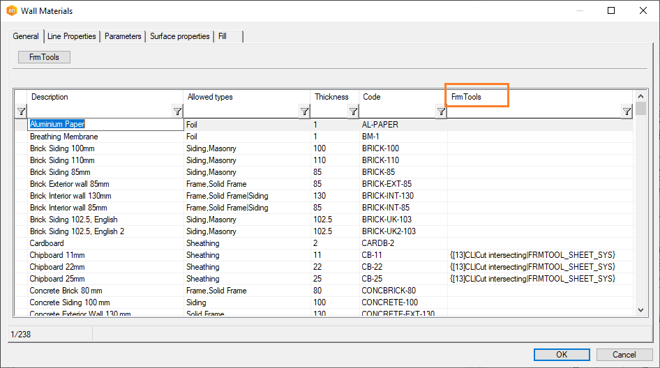
The update function adds the field FRM_TOOL to the customer-specific layer libraries, for example:
custom/complibs/layers
custom/complibs/wall_layers
The field can be used for selecting a default framing tool for a layer.
-
Insulation and Sheathing Libraries
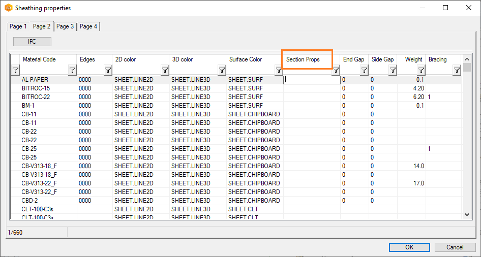
The update function adds the field SECTPROP to the databases of the customer-specific insulation and sheathing libraries:
custom/dbases/d_SHEETLIB
custom/dbases/d_INSULATIONLIB
-
Wall Framing Details
The update function adds new framing details to the customer-specific wall framing detail library. The databases to be edited are:
custom\dbases\d_DET_FRAME - Wall frame details
custom\dbases\d_DET_CL_LEV - Clip levels
custom\dbases\d_DET_PROF - Pieces of frame details
-
Pieces of Frame Details
The update function adds the following fields to the customer-specific DET_PROF database (custom/dbases/d_DET_PROF):
ICUT_EDGE - Cut edge
ICUT_TOP - Cut front
ICUT_BOT - Cut back
The parameters can be used to control the clipping of top or bottom plate in a wall frame according to an inclined structure (roof).
This feature can be implemented as customization.

-
Steel Environments
The update function adds the following details to the customer-specific DET_PROF database (custom/dbases/d_DET_PROF):
ST-BPSILL
ST-BPTRACK
Metric steel environments
The update function adds the following new fields to the WALLFRM database in the customer-specific wall framing macro component library:
BLK_OVERLAP
BLK_OVERLAP2
BLK_OVERLAP3
TRS_SPAC
TRS_SPAC2
TRS_SPAC3
The udpate function updates the custom/details/material_specs file - default material specifications for wall panels.
The update function fixes the clip levels in the DET_CL_LEV database of the customer-specific wall frame detail library (custom/dbases/d_DET_CL_LEV). The following details will be fixed:
ST-WSIDE-PAR
ST-WSIDE-PAR3
ST-WSIDE-PAR3
Imperial steel environments
The update function adds the field FRMTHICK_RQ for the customer-specific wall framing tools.
From version 2019 (25.0) to version 2020 (26.0)
- Building Component Libraries
The update function adds the following fields to the databases of customer-specific building component libraries (or macro component libraries):
- ITEM_CODE - Item. This field allows you to enter an external system code that will be included in the material collection.
- IFC_PROP

- Eaves Trim Library
The update function adds the ORDER field to the custom/complibs/eave_trim/d_EAVE_TRIM database.

- Roof accessories
Improvements have been made to the positioning of the lead-ins in the roof accessories library on the roof slopes. If you use the standard library, no action is required.
If the roof_accessories library is located in the custom folder, the update function adds the INPUT_FUNC field to the custom/complibs/roof_accessories/d_ROOF_ACCESSORIES database. You can enter the name of the ADT program that is run when the component is added as tge field value. The basic software delivery includes two different programs:- XDirOppSlope.prg
- YDirOppSlope.prg
The programs turn the component's local x- or y-direction perpendicular to the roof slope.

The format file connected with the database has also changed. The old format file was named as macrolib_brw. The new format file is roofacc_brw. It is located in the system/forms folder. Change the name of the format file in the custom/complibs/roof_accessories/complibs.xml file.
Find the row:
<ScreenForm>macrolib_brw</ScreenForm>
Change the name of the format file:
<ScreenForm>roofacc_brw</ScreenForm>
- Floor or ceiling sheathing tool library
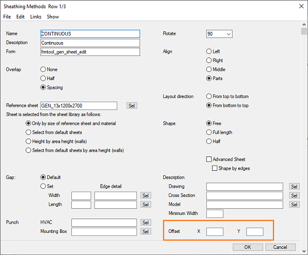
The update function adds fields for defining an offset for the sheathing origin to the database of the customer-specific floor and ceiling sheathing tool library (for example custom/complibs/frmtool_gen_sheet_cst/d_FRMTOOL_GEN_SHEET):
- OFFSETX - Offset X
- OFFSETY - Offset Y
- Cladding library
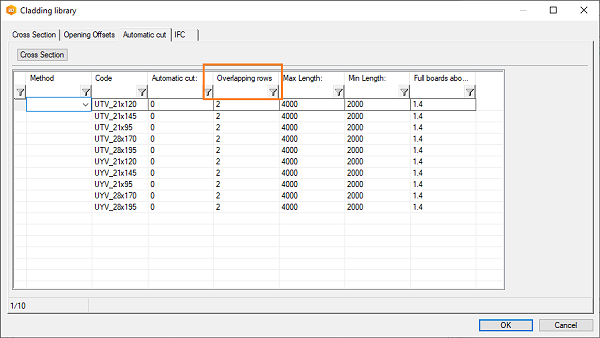
The update function adds a field for defining the number of overlapping board courses when automatic cut of siding boards is enabled to the database of the customer-specific cladding library (for example custom/complibs/cladding_cst/d_FRMTOOL_CLADDING):
- CUTROWQTY - Overlapping rows
- Panel template drawings
The update function adds a new layer “179 Bracing” to the customer-specific panel template drawings.

- Insulation library
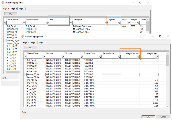
The update function adds the following fields to the custom/dbases/d_INSULATIONLIB database.
- INJECTED - Injected
- VOLUME_WEIGHT
- ITEM_CODE - Item. This field allows you to enter an external system code that will be included in the material collection.
- Contact person library
The update function adds the field COMPANY to the custom/dbases/d_ADDRESS_BOOK database.

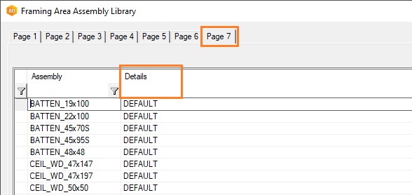
- Framing area assembly library
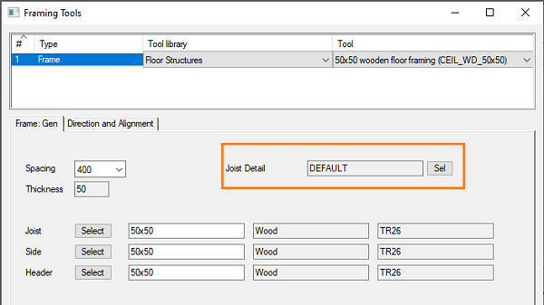
The update function adds the field INT_PCE_DET to the custom/dbases/d_FRMASSY database. The value in the field is read for the parameter Joist Detail in the framing tool.
- Sheathing library
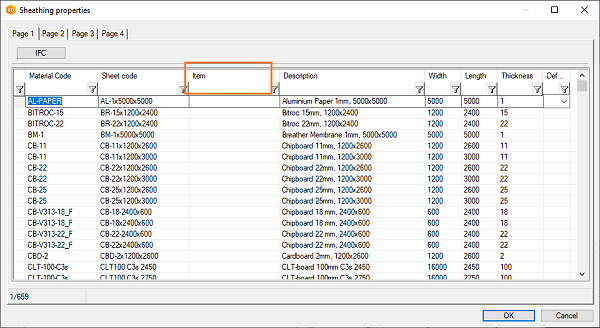
The update function adds field ITEM_CODE to the custom/dbases/d_SHEETLIB database. This field allows you to enter an external system code that will be included in the material collection.
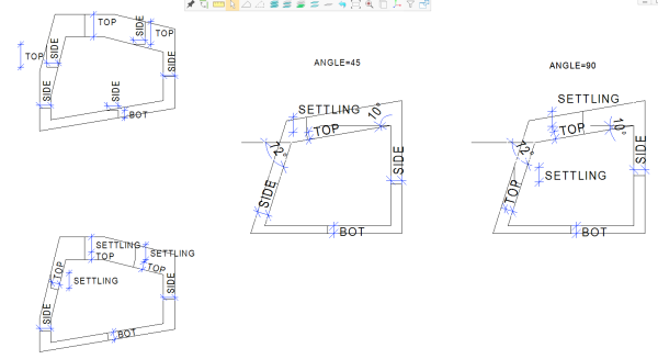
- Settling and installation spaces for a slanting opening in a log wall
The update function checks, if the application development program LOGW_OPEXT.PRG has been customer-fitted. The application development program calculates the installation spaces for openings in a log wall. Two new parameters can be used in calculation for calculating the settling and installation spaces for slanted openings. If the program is customer-fitted, the new parameters need to be added manually to the file. If parameters are not defined, the installation spaces are calculated as before. The new parameters are:The possible customer-fitted program is located in the custom/macros/logmach folder. Send the file LOGW_OPEXT.PRG to Vertex BD helpdesk (bdhelp@vertex.fi) for adding the parameters.
- SETTLING - Vertical settling space at the top edge.
- ANGLE - The parameter defines how the slanted edges are handled.
From version 2018 (24.0) to version 2019 (25.0)
-
Draft settings of a view in a panel drawing
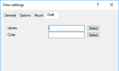
The properties of a view in a panel drawing has a new tab Draft for defining the drawing properties of lines according to material thickness. The feature is intended to be used in steel structure design. The tab has been added to the format file in the system folder, system/forms/stred_view. If you are using a customer-fitted format file, the system update function will rename it: custom/forms/obsolete_stred_view. After this, the program uses the format file in the system folder.
-
Floor or ceiling sheathing tool library
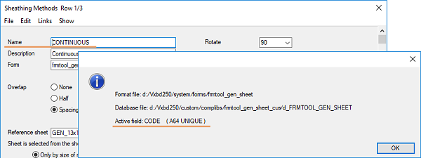
The function sets the type of the field CODE (Name) in the customer-fitted FRMTOOL_GEN_SHEET database (for example custom/complibs/frmtool_gen_sheet_cus/d_FRMTOOL_GEN_SHEET) to be UNIQUE.
-
Wall panel horizontal batten tool library
The function adds a new field to the customer-fitted FRMTOOL_HBATTEN database (for example custom/complibs/frmtool_hbatten_cus/d_FRMTOOL_HBATTEN).
- PCE_MIN_LEN – Batten minimum length
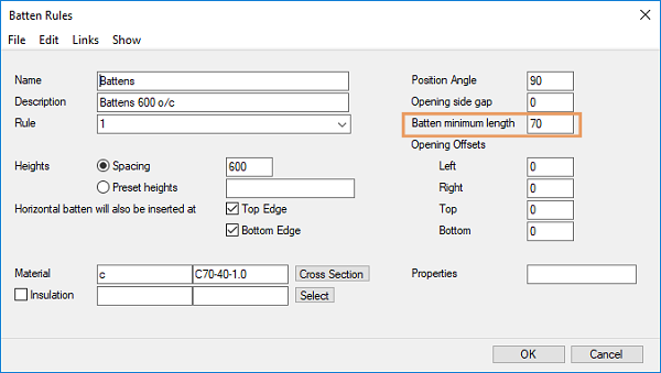
If the format file connected to the database is customer-specific, you must also add the field to this format file, or you can start using the format file in system folder (system/forms/frmtool_hbatten). The file in the system folder will be used when you rename the file in the custom/forms folder.
-
Property Data of Profile Library
The function corrects the shape definitions of certain profiles in the profprop file of a profile library. The libraries are hfrhs, hfshs, cfrhs and cfshs. The new or updated lines are:
"mat_param= S.SHAPE RHS"
"mat_param= L.MATER.CODE S235JR|S275JR|S355JR"
From version 2017 (23.0) to version 2018 (24.0)
Wall structural layer library
The function increases the lengths of the following fields in the customer-fitted WALL_LAYER database (custom\complibs\wall_layers\d_WALL_LAYERS):
- CODE - Code, new length 64 characters
- DESCRIPTION - Description, new length 255 characters

Horizontal blocking of wall panel
The function adds new fields for a second horizontal blocking definition to the customer-fitted WALL_FRM database (for example custom\complibs\walls\vakiorakenne\d_WALL_FRM).
- BLK2_ON – Check box for swithcing horizontal blockings on or off
- BLK2C, BLK2F, BLK2LIB, BLK2MAT, BLK2W - Cross section data
- BLK2_HT – Height of the horizontal blocking
- BLK2_TYPE – Type of the horizontal blocking

If the form file connected to the database is customer-specific, you must also add the field to this form file, or you can start using the form file in system folder.
Profiles of wall frame
The function adds a new field to the customer-fitted DET_PROF database (custom\dbases\d_DET_PROF).
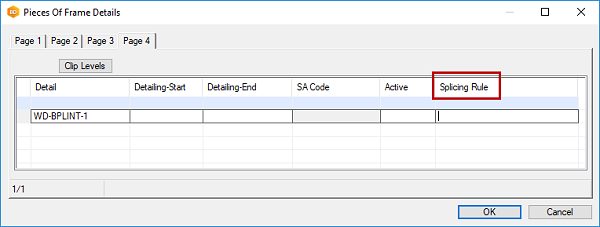
- SPLICING_RULE - Splicing rule
The format of the splicing rule is the same as in the detail file (for example custom\details\wd.xx). If the Splicing rule has been entered in the database, the profile will be cut according to the rule. Otherwise the top_plate_splice and bottom_plate_splice rules defined in the detail file will be used.
Cladding tool library
The function changes the type of the customer-fitted library and renames the database.
- The database type is now frmtool_cladding, previously it was macro.
- The database name is now FRMTOOL_CLADDING (custom\complibs\cladding_sys\d_FRMTOOL_CLADDING), previously it was CLADDING_SYS.
The function adds new fields to the customer-fitted FRMTOOL_CLADDING database:
- MIN_WIDTH - Minimum width
- MAX_NOTCH - Maximum notch


If the form file connected to the database is customer-specific, you must also add the field to this form file, or you can start using the form file in system folder.
Framing details
The function adds new fields to the customer-fitted FRM_DETAILS database (custom\dbases\d_FRM_DETAILS).
The following parameters are used in the framing tool of an inclined layer:
- INCLINE_CUT - Cut plane
- INCLINE_CUTMODE - Cut mode
- CUTOFFSET_TOP - Offset from top
- CUTOFFSET_BOT - Offset from bottom
The parameters define the cutting of parts according to the inclined surface.

The following parameter is used in the beam combine tool:
- COMBINE_ID - Combine Id
The parameter defines the combining id based on which beam on top of each other will be combined.

If the form file connected to the database is customer-specific, you must also add the field to this form file, or you can start using the form file in system folder.
Floor or ceiling sheathing tool library
The function adds a new field to the customer fitted FRMTOOL_GEN_SHEET database (custom\complibs\frmtool_gen_sheet_sys\d_FRMTOOL_GEN_SHEET).
- SHEET_MIN_W - Minimum width
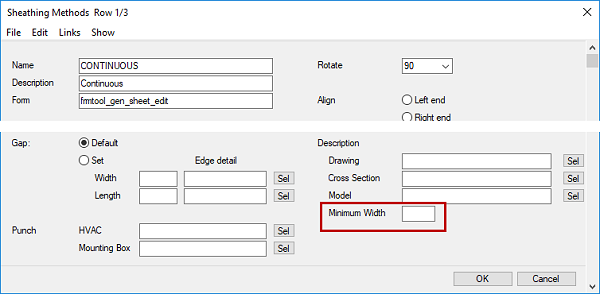
The parameter can be used to define the minimun width of sheets. Smaller sheets and sheet strips will be removed.
Panel template drawing library
The function adds a new field to the customer fitted PANEL_DWG database (custom\complibs\panel_dwg_sys\d_PANEL_DWG):
- ORDER - Order

This field can be used to set the template drawings in the desired order in the dialog box where you select the template drawing to be used when creating panel drawings.
From version 2016 (22.0) to version 2017 (23.0)
Wall Panel Settings
In version 2017 (23.0), wall panel settings are moved from the system settings (vxsettings.xml) to the component library. The aim is to simplify editing and saving customer-specific settings. A library saved in the ../system/complibs/wallpanel_sys folder is included in the standard software delivery.
If the system settings have been customer-fitted (the ../custom/vxsettings.xml file exists) so that the keywords related to wall panel settings have been edited, but the customer-specific wall panel setting library does not yet exist, the update function adds a library called walpanel_cst to the ../custom/complibs folder.
After this, you can select either customer-specific settings or the system settings in the Wall Panelizing Settings dialog box.
The functionality will be further developed in the future service packs of the main version. The system administrator will be able to edit the existing settings and save new ones.
Studs Under Trusses
A property Under Trusses can be selected for the wall frame layer tool. This property always adds a frame stud at the location of a truss above the wall. The update function adds a new field UNDER_TRUSSES to the customer-specific framing tool (database WALL_FRM) for this property.
If the form file connected to the database is customer-specific, you must also add the field to this form file, or you can start using the form file in system folder.
Wall Frame Detail in Steel Environment
The update function checks if the customer-specific wall frame detail library (database DET_FRAME) has a detail ST-SIDE-FR. If the detail is not found in the custom folder, it is copied from the database in the system folder.
The function also copies the profiles and clip levels (DET_PROF and DET_CL_LEV) connected to the detail from the system to the custom folder.
Does not affect the wood environments.
Dimension Lines in Panel Drawing
The update function adds a new field VIEW_GEOM to the dimensioning database of panel drawing views (VMEAS_SETUP). When the field's value is 1, and the presentation method of the object is 3D, the dimension line points are searched from the view's geometry. Dimensioning according to the view's geometry dimensions the points that are visible in the drawing. However, dimensioning can not always be done this way, because not all the points of an object to be dimensioned are necessarily visible. For example, the object may be behind another object whose geometry covers the object to be dimensioned.
When the field's value is 0 or empty, the dimension line points are searched from the objects to be dimensioned (default method).
If the form file connected to the database is customer-specific, you must also add the field to this form file, or you can start using the form file in system folder.
File Registers in Template Projects
The update function changes the description field (DESCRIPTION) in the file registers (database FILEREG) of template projects to M type. This change is necessary for supporting Chinese characters.
Building group library
The function checks if the building group library (database BLDGMOD_CUSTOM) in the customer-specific component library has the CODE field, and adds it if necessary.
Sweep Operations in Models
The sweep operation of the Vertex G4 modeler has been changed. The update function checks all the model files (*.vxm) in the ../custom/complibs and ../shared/picts folders. If the old sweep operation has been used in the models ,the function solves and saves the models. First, a backup is made of the models to the ../user/sweep_backup folder.
The fixed models are listed in the message that opens after the update function has been performed. If there are files that cannot be fixed with this function in the custom or shared folders, they will be listed in the message under the title "Following models have old sweep-features". Such files are models which contain models (models designed with the Vertex G4 modeler have been imported to the model), for example. Open and check these models.
Default Rendering Materials
The function checks the default rendering materials set in the linking database of rendering materials (LWMAP). The materials that cannot be found in the rendering material library are opened in a database view. You can select new materials by clicking the Browser button in the database view.
From version 2015 (21.0) to version 2016 (22.0)
-
Customer-specific Components
Adds a row to a library of type BDSMACRO/WFRM (wall panel macros). The function adds a row which will enable the wall panel break point macro in the user interface.
Customer-specific electrical symbols:The function copies the MACRO_ELBOX (electrical boxes) library from the system to custom folder. System symbols are removed, and all the customer-specific electrical symbols from libraries of type BDSMACRO/WFRM (wall panel macros) are copied to the library. If the MACRO_ELBOX library already exists, or customer-specific electrical symbols cannot be found, the procedure is not performed.
After updating, the electrical symbols can be selected from the building component browser, from the folder Electrical boxes.
Adds a new row to a library of type BDSMACRO/HWR or BDSMACRO/HWR2 (angle brackets):
- IFC_PROP - IFC-set. Defines the property data to be exported to an IFC file.
Customer-specific Framing Libraries
Adds new rows to the SHEETLIB database (sheathing properties):
- GAPX, GAPY - Different installation gaps in X and Y direction
- AREA_WEIGHT - Weight
- MATER_DESCR - Material description
- IFC_PROP - IFC-set. Defines the property data to be exported to an IFC file.
Adds new rows to the INSULATIONLIB database (insulation properties):
- AREA_WEIGHT - Weight
- MATER_DESCR - Material description
- IFC_PROP - IFC-set. Defines the property data to be exported to an IFC file.
Adds new rows to the FRMASSY database (framing area assembly library):
- DEF_JNT_LIB - Default joint library
- DEF_JNT_CODE - Default joint code
Adds a new row to the DET_PROF (pieces of frame details) and FRM_DETAILS () databases:
- MOUNT - Mounting. Defines the mounting data of a profile. May have the following values:
M = manual, a piece to be fixed manually
L= loose piece.
The data can be edited in the profile properties.
Customer-specific System Settings
Negative color numbers of lines and hatches have been changed to positive in the system settings. This change is related to defining the color of basic geometry, which was fixed earlier. The function updates the change to the settings in the custom folder.
Customer-specific Writers of NC Link
NC menu is located on the Output tab in the new user interface. The transfer file writers are now defined in the system settings with the keyword nc_output (BDSXX keyword group). The keywords are of the following format:
NAME WRITER SETUP
NAME = Name to be shown to the user
WRITER = Name of the NC writer
SETUP = Name of the setup file
The update function converts the custom fitted writers automatically to the new format. The update function takes care of converting the NCCOMM_MAIN commands located on the barmenu in previous versions and the nc_setup keywords, and adds the custom fitted functions in the new NC menu. The collected nc_output keywords need to be checked after the conversion.
Customer-specific Commands
A custom tab is generated of the custom fitted commands, unless it already exists. Commands already located on the ribbon bar, are not copied. Only the customer-specific commands are copied (for example layer groups). Group titles and command descriptions according to the old menu bar are also copied at the same time. It may be necessary to change the order of the commands on the tab afterwards. It can be done by editing the customtab.xml file.
From version 2014 (20.0) to version 2015 (21.0)
Layer library for floors, ceilings and roofs
In the version BD 2015, the layers for floors, ceilings and roofs are defined in the layer library. The system library is in the system/complibs/layers folder. The system update function converts the old customer-specific material layer library database ../custom/dbases/d_LBMAT into a new type layer library in the ../custom/complibs/layers_custom folder. The format of the library is defined by the system and the contents are read from the old customer-specific database. The update function does not know the types of the layers. After the update procedure, you must define the types manually in the layer_custom library.
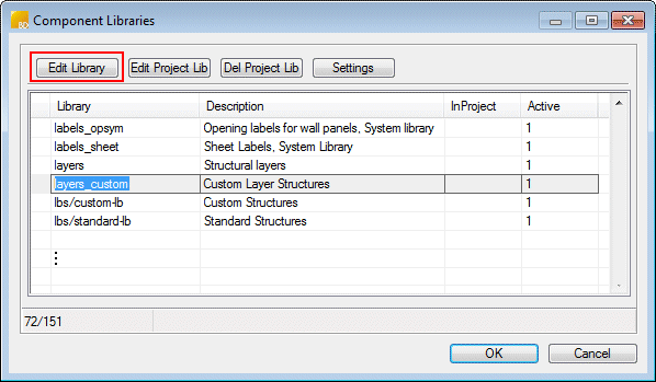
- Select System | Libraries |
 Libraries. The Component Libraries database view opens.
 - Move to the row layers_custom | Custom Layer Structures.
- Click the Edit Library button at the top.
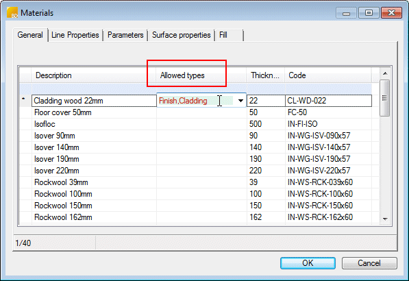
The Allowed types field must be defined for each row in the library. The field defines what kind of materials are available according to the type selection. It determines what options are available for each layer type in the floor, ceiling and roof selection dialog box.
The default drawing properties of the edges and hatches of floors, ceilings and roofs have been defined in the system settings with the keyword area_layer_props.
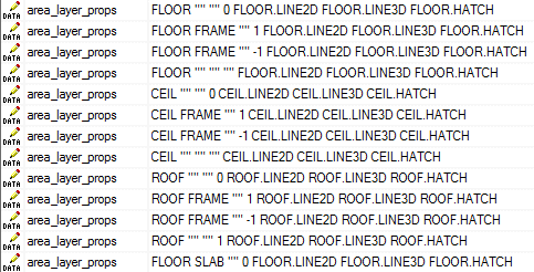
The properties can be overridden in the layer library by setting the drawing properties for each layer on the Line Properties tab. If the rows in the database are empty, the default properties defined in the system settings will be used.
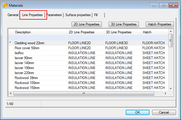
In the BD 2015 version, it is possible to guide the material's direction with a direction angle in the layer parameters. This parameters affects the direction of both the accurate and coarse presentation. If you wish to use the direction angle, you must also enter a value for the usable width. The direction angle and usable width are used together mainly for the UTV and UYV siding materials. They have been designed to utilize these parameters. Examples can be found in the system's layer library.

- Select System | Libraries |
Floor, ceiling and roof libraries
The update function also creates a new floor, ceiling and roof library ../custom/complibs/lbs/custom-lb, which is displayed in the library user interface with the name Custom Structures. The library is ready for use after the update.

Updates to library structures and contents
The function also makes the following updates related to the structures of the library databases, which do not require any changes to the contents:
- The alignment definition is fixed in the framing tool database for floors and ceilings (already included in a service pack for the 2014 (20.0) version, but it is checked during the update to 2015 (21.0) version). A parameter FRM_ALIGN is added to the database, and the value of the possible old ALIGN parameter is set to it.
- Missing fields are added to the profile database of wall panelizing.
- A BRACING field, which describes the stiffening feature of a sheet, is added to the sheathing library. At this point, it is mainly related to designing CFS (Cold Formed Steel) structures.
- Material data (strength class) has been added to the material_specs file and framing databases for wall panelizing in steel environments. It does not affect the wood environments.
From version 2013 (19.0) to version 2014 (20.0)
-
Window and door library browser
The databases of customer-specific window and door libraries are renamed:
- d_WIN_CUSTOM -> d_WINDOWS
- d_DOOR_CUSTOM -> d_DOORS
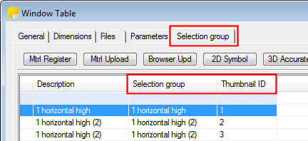
- Selection group (SELCLASS) - The function copies descriptions from the …\dbases\COMP_TYPES database to the SELCLASS field of the DOOR/WINDOW database.
- Thumbnail ID (THUMBNAIL_ID) - For the preview image.
Wall structural layer library
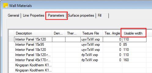
The field Usable width (USABLE_WIDTH) is added to the wall_layers data base of the wall structural layer library. The usable width is the pitch of a single board. The usable width is intended to be used together with the direction angle of the siding when a parametric siding material is used. Together, they control the direction of the siding, the board width in an accurate presentation and the rendering material in a coarse presentation. This enables both vertical and horizontal claddings of varying widths by using just one rendering material. The UTV/UYV materials are included as an example in the standard delivery of the 2014 version.
Wall panel corner joints
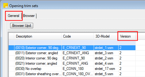
The field Version (CMP_VERS) is added to the corner joint database STRUCTDET_CST. It defines the type of the corner joints. The new corner joints are added to the library in accordance with the new type. The old joints remain the same.
Wall panel framing tool
The new parameter Properties has been added for the wall panel framing tool Horizontal Battens. The properties refer to those defined in the PIECE.SETUP keyword group of the system settings. If the properties have not been specified, the property group FRAMING.WALL_HB is used. The update function adds a new parameter in the customer-specific tool library, if one is available.
Horizontal structure framing tool
The frame parts of horizontal structures (framing or panel), sheets in sheathings, and claddings in cover layers are now specified layer-by-layer using framing tools, as is the case with wall panels. The system update function connects the framing tool to the structural layer of the structure specified in the customer-specific horizontal structure's structural library (LBCOMP database) if the layer type is FRAMING and the corresponding item can be found in the framing area library (FRMASSY database). The connection is performed automatically for frame layers. You can select whether to connect the tool to other batten layers as well:
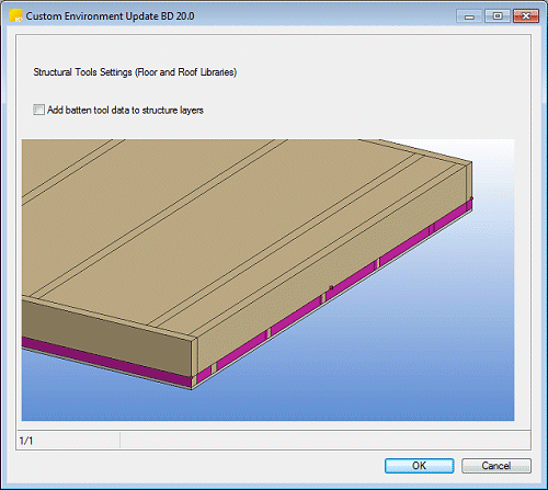
When parts are added to the structure, they are added for all layers to which a framing tool has been connected. If you have previously added parts to the batten layers, do not select the checkbox Add batten tool data to structural layers, in which case parts will still not be added to the layers in question.
The same conversion is performed on the horizontal structure of an old project, when the project is opened. The tool is not automatically fixed to the sheathing layer.
In older versions, it was possible to select the Joist cross section for the frame layer part and then specify the rest of the parts (Side, Header) by using the same cross section with the option Default, leaving the cross section fields empty.
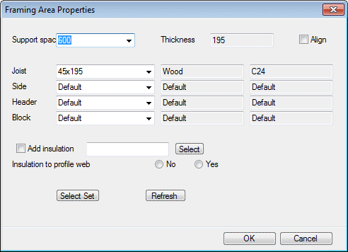
In version 2014 (20.0) this is no longer possible. A cross section must be defined for each part (if the cross section field is empty, the part cannot be added). The update program tries to implement all the necessary changes automatically.
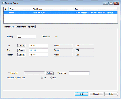
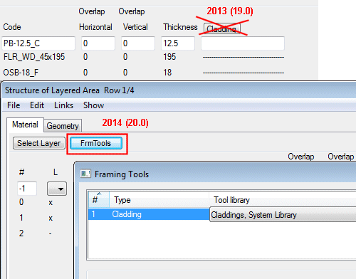
The update function removes the Cladding button from the Structure of Layered Area view. The cladding is defined using the framing tool Cladding.
Materials removed from the rendering material library
Old fixed materials have been removed from the rendering material library, and they have been replaced with new parametric materials (such as paints). The update function checks the linking database (LWMAP) of the rendering materials in the custom folder, and re-links the materials. The function aims to re-link the materials automatically. If this is unsuccessful, a database view is opened, where all materials that are no longer available have been compiled. You can select new materials by clicking the Browse button.

It is recommended to select parametric materials, if possible. Parametric materials can be found in the following browser folders:
- Parametric paints - System/Materials/Paints.
- Parametric tiling - System/Materials/Tiles, material BASIC TILE.
- Parametric siding - System/Materials/Wall/Siding, parametric, material WOODEN BOARD.
- Parametric varnished panel - System/Materials/Wall/Siding, parametric, material UTV varnished (latter).
For example, you can find a new parametric material to replace the old GREY 95% material as follows:
- Click the Browse button.
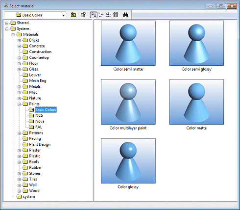
- Select the browser folder System/Material/Paints/Basic Colors.
- Double-click the material Color semi matte, for example.
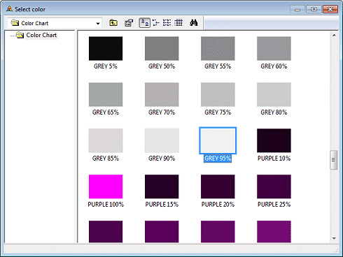
- Click the Color Chart button.

- Double-click the color GREY 95% in the browser.
- Confirm by clicking OK.
