Edit the Drawing-model Pair Button Menu
The button menu for drawing-model pairs contains a button for the drawing-model pairs that have been selected for use in the building. The standard delivery of the program includes a button menu definition for a building with 10-13 floors. The number of floors varies in different localization environments. When you enable drawing-model pairs, the buttons automatically appear in the button menu for those floors for which a definition is found. If you need buttons for more floors, they must be defined in the button menu separately.
The system button menu is defined in the system/setup/mousec file. Copy the file to the custom/setup folder and open it for editing in, for example, Notepad.
Adds rows for the buttons to the file.
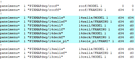
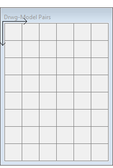
The buttons are 34 x 34 pixels in size. The grid of the button menu starts from the top left corner and continues to the right in the X direction and down in the Y direction. The position of each button is specified by an X/Y offset, for example d34 d34.
- The position of the first button is 0 0. The position of the other buttons on the same row is d34 d0 (offset 34 right in X direction, 0 down in Y direction).
- To start a new row, enter the button an offset of d34 d34. The offset of the other buttons on the same row is d34 d0 (34 right in X direction, 0 down in Y direction).
Restart Vertex after editing the custom/setup/mousec file.
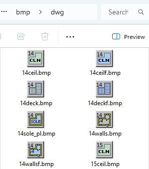
The standard delivery of the program includes bitmaps for the buttons of the drawing-model pairs from the basement to the roof and 20 floors between them. If you need more floors, you will also need bitmap files (bmp) for their drawing-model pairs. You can copy an existing bitmap file from the system/bmp/dwg folder and paste it to the custom/bmp/dwg folder. Edit the bitmap files and add them to the mousec file.