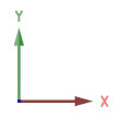
Coordinate System
- the x axis direction is horizontal and y axis direction is vertical in a drawing

- the z axis direction is vertical in a model

If necessary, you can temporarily enable a local coordinate system. You can define the direction of the local coordinate system yourself. The local coordinate system is not saved in the drawing or model.
In both the global and local coordinate systems, you can use the relative coordinate system to define distances.
Absolute origin
The origin of the global coordinate system is the following regardless of the cursor location:
- In the model window 0x,0y,0z
- In the drawing window 0x,0y
In the drawing window, the absolute origin locates in the lower left corner of the drawing limits, when a new drawing is created.
In the model window, the absolute origin locates in the origin of the planes.
- The planes are visible by default.
- The origin (=center cross) of the first sketch of the part model is located at the absolute origin point.
In the model, you can show or hide the absolute origin:
- Select
 >
>  User Preferences >
  Drawings, Models.
 - Select the View tab.
- Select or clear Model: Show Model Origin.
The coordinates X,Y,Z show the distance between the cursor and the absolute origin. Click the status bar to display the coordinates X,Y,Z in the right end of the status bar.
Local origin
The origin of a relative coordinate system, or the local origin, is located in the point last selected. In other words, the location of the local origin changes as points are selected.
The coordinates dx,dy,dz show the distance of the cursor from the point last selected. The status bar displays these coordinates by default. You can view the coordinates X,Y,Z and dx,dy,dz in turns by clicking the status bar.
Visibility of G4 model's auxiliary planes when a new model is created
- You can adjust the visibility of auxiliary planes in the system settings:
 >
>  System Preferences >
  Edit
Edit Administrator's View
- Vertex Settings > 3d > Set base planes visible when new model is created
- Values of the keyword baseplanesvisiblewhencreated:
- 0 = auxiliary planes are hidden.
- 1 = auxiliary planes appear in a new part model.
- 2 = auxiliary planes appear in a new assembly model.
- 3= auxiliary planes are visible in both part model and assembly model (default).

