Define a Perspective View
Architectural
With this function, you can define a perspective view of a building. You can define the view either from outside or inside the building, either in the floor plan drawing or in the model. If you define the perspective view in the model, first set the model in the desired view.
- Do either of the following:
- Select Output | Drawings |
 Define Cross Section View
 Define Perspective
View.
 - Select the function in the project's document browser:
- Move the cursor on the title Architectural documents / Perspective views.
- Right-click to open the context-sensitive menu.
- Select Define Perspective Drawing.
- Select Output | Drawings |
- Select a drawing generation model:
- In order to produce an outside view, you can use the drawing generation model Elevations.vxm.
- In order to produce an interior view, you can use the drawing generation model Interior.vxm.
- If you define the perspective view in the floor plan drawing, do as follows:
- Select the location of the view point.
- Select the direction.
- Type a label for the perspective view.
- Type a name for the perspective view.
- After you have defined the perspective drawing, you need to update it. You can add the updated drawing on a drawing sheet.
 Note
Note
- When you define the perspective drawing in the floor plan, the default values for the view
point height, inclination and viewing angle are displayed in prompts on the status bar. You
can change these default values as follows:
- Before selecting the location of the view point, you can select its height (Z
coordinate) and inclination (°) by clicking the Z button. Enter
the values in the text box. Enter the Z coordinate relative to the floor base height.

- Before selecting the viewing direction, you can select the viewing angle (°) by
clicking the Angle button. Type the value in the text box.

- Before selecting the location of the view point, you can select its height (Z
coordinate) and inclination (°) by clicking the Z button. Enter
the values in the text box. Enter the Z coordinate relative to the floor base height.
- If necessary, you can create a new drawing generation model specially for producing perspective views, see Edit the Drawing Generation Model Settings.
Example
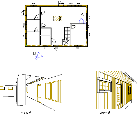
In the example below, two perspective views have been defined in the 2D drawing of a building with labels A and B. In both perspective views the elevation position of the view point is 1500 mm, slanting angle is 0 and the width of the viewing angle 75 degrees. The perspective views have been given the names view A and view B.


