
Define Cross Section Terrain View
Architectural, Framer
If you want a simple ground level line in the elevation view that exactly follows the shape of the terrain at the exterior wall, you can create such a ground level line using the Define Cross Section Terrain View function. The depth of the section created with this function is automatically 1, which means that the geometry of the drawing generation model 1 mm away from the section line is included in the section.
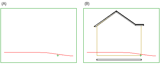
The drawing generation model must include terrains. If necessary, edit the drawing generation model settings, see Edit the Drawing Generation Model Settings. If the drawing generation model does not include objects other than terrain, only the terrain line (A) appears in the section view. The section view (B) is formed from a drawing generation model that also contains other objects of the building model.
The section is created by clicking the walls, so select the function in the drawing-model pair in which the walls are located or in which they are set visible.
- Activate a drawing window.
- Do one of the following:
- Select Output | Drawings |
 Define Cross Section View >
  Define Cross Section Terrain View.
 - Select the function in the building's document browser:
- Move the cursor on the title Architectural documents / Sections.
- Right-click to open the context-sensitive menu.
- Select
Define Cross Section Terrain View.
- Select Output | Drawings |
- Select the drawing generation model.Note: Select the model that contains terrains. The objects included in the drawing generation model are defined in the drawing generation model settings.
- Click one or more walls.
- Select Confirm.
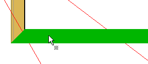
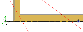
The program adds a section line to the outer surface of the wall. You can widen the section by moving the end points of the line using the round grip points.
Update and open the section by using the function Update and Open a Vertical Section.
- The terrain line can be a clipping or dashing line, see Ground Level Line From Terrain Model.
- You can use a section view that shows only the terrain line (A) by adding the view on top of a view on the elevation drawing sheet to show the surface of the terrain, for example. However, the terrain line does not clip or dash the geometry in another view, even if the terrain line has this property.
- You can add height data to the view by using the Add a Height Symbol function.