
Add a Profile Using Two Different Reference Points of the Cross Section
Profile Structure Design
General
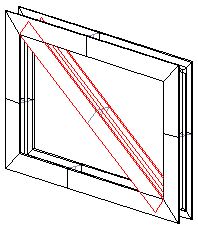
The cross section of the profile is swept as a profile between two selected points in such a way that different points are used for the start and end point of the profile.
- To have the profile part set to the desired plane, you have to define the sweep plane.
- A profile part created this way is a part fixed to the assembly.
A profile part created this way
- Is a part fixed in place. If you want to fix it in place with constraints, you must first detach the part.
- The part does not follow the points clicked in the profile insert if the reference parts are moved or rotated.
This method is so complicated that we recommend making a guide curve part (jig or skeleton) to guide the profile to its right place instead. Using a guide curve part, for example, changing the dimensions of the structure is very easy.
- See instructions on https://kben.vertex.fi/g4/. Select Vertex G4 and from there, Self-study material > Profile structure course.
Add a profile using two different reference points
- Start adding a profile:
- Vertex G4: On the
 tab, in the Add group, select
  Add Profile.
 - Vertex G4 Plant: On the
 tab, in the Steel Structures group, select Add Profile.
 - Select the contextual function:
 Add > Profile
- Vertex G4: On the
- Select a profile cross section from the browser:
- By using the context-sensitive function
 Select or
 - By double-clicking the cross-section.
- Click the profile, drag it a little and release the mouse selection button.
- By using the context-sensitive function
- Select the table ID determining the profile size from the list.
- Or if the profile does not have a dimension table, enter the dimension in the dimension table that opens
- If necessary, attach item data to the profile part.
- Click the location of the starting point of the profile.
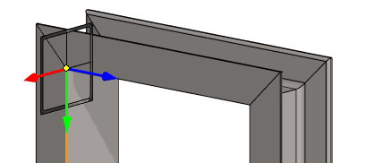
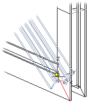
- Define the sweep plane, i.e. the plane parallel to which the profile is swept.
- Select the auxiliary function
 .
. - Click a planar face.
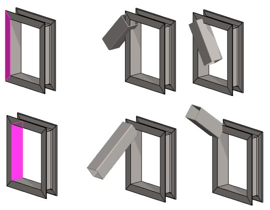
- The above image shows the effect of two different surfaces on the reference plane.
- Select the auxiliary function
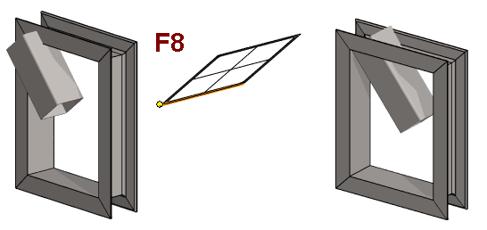
- Use the F8 key or the auxiliary function to change the location of the reference point of the profile the cross-section
- The program opens the cross section and asks to click the new the reference point.
- Click a reference point from the cross section.
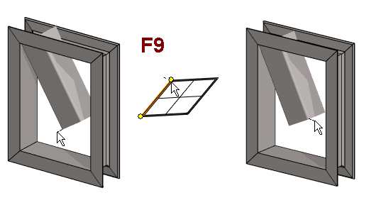
- Use the F9 key or the auxiliary function to change the location of the reference point of the profile end

- The program opens the cross section and asks to click the new the reference point.
- Click a reference point from the cross section.
- Select the profile end point.
- When you want to stop adding profiles:
- Select another function or
- Press the Esc key.
Note:
- You can also use the context-sensitive function
 Add> Profile.