
PI Schema Link
Process and Instrument Design
Select functions between a 3D model and PI schema.
- Selecting a Component from a Schema
- Marking a Device Indicated in the Schema to a Model
- Marking a Device Indicated in the Schema into a Schema
- PI Schema Link Settings
- Comparing a Model and PI Schema
- Marking Positions Missing from the Active Model into the PI Schema Tree
- Open the 3D model and corresponding PI schema in the working window. You can select functions, when the 3D model window is active.
- The PI schema link also functions in a local assembly.
- Start the video help by clicking Shift + left mouse button on the button.
Selecting a Component from a Schema
- On the
 tab, in the PI-schema Link group, click Select Component From PI-schema.
 - Click a device or line in the schema.
- Add the component in the 3D model.
Marking a Device Indicated in the Schema to a Model
The modeling status of the position is indicated with a color.
- On the tab, in the PI-schema Link group, click Comparison, and select Mark PI-schema's Equipment in Model.
- Click a device symbol or a line in the PI schema. Select Confirm.
- The component status can be changed later in the component data by double-clicking the component in the schema. This displays the COMPONENT DATA dialog box.
- In the Line Position or Equipment Position field, click the PI button. The Position Modeling Status dialog box is opened.
- The modeling status of the position is indicated in the diagram with a color. Select one of the following:
- In the PI schema only – GRAY
- In progress 3D – RED
- Also in 3D Model – GREEN
- Click OK.
The coloring is shown in real time. Both your own work status and the work statuses of other users are shown.

Marking a Device Indicated in the Schema into a PI Schema
- On the tab, in the PI-schema Link group, click
 Mark Model's Equipment in PI Schema.
 - Click a pipe component in the 3D model. Based on the attribute data of the selected component, the right diagram line or equipment symbol is searched from the opened PI schema. If found, it is marked.
PI Schema Link Settings
- Open the 3D model in the working window.
- On the tab, in the PI-schema Link group, click
 Settings of the PI-link.
 - Selecting a component from a schema, the default is:
 Set the Selected Element to State "In Progress".
- Marks the PI-schema According to the Modeling States.
 Once this has been selected, the color will change in the schema in real time.
- Edit the settings, if necessary.
- Edit the marking color of the device selected from the model to your liking. Click the menu field:
 and select a color from the palette.
 - Click OK.
Comparing a Model and PI Schema
- On the tab, in the PI-schema Link group, click
 Compare Model and PI-schema.
The Compare 3D Model and PI Schema dialog box opens. In it, you can see which positions are shown in the model and/or schema.
- Zoom, or limit an area for viewing.
Marking Positions Missing from the Active Model into the PI Schema Tree
- Open the 3D model and PI schema. Place the windows next to each other.
- On the tab, in the PI-schema Link group, click
 Mark the Missing Positions to the PI-schema Tree.
Collect elements of the opened 3D-model and PI-schema to a common comparison database. Based on this, you can mark the elements missing from the 3D-model to the tree in PI-schema.
- Mark - Your selection is marked in the PI schema.
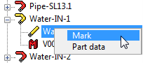
- Part Data - The pipeline data is opened. Supplement the information.
- Mark - Your selection is marked in the PI schema.
- Move the cursor to the first position in the schema tree.
- Select the context-sensitive function Update Position Tree. The tree is expanded.
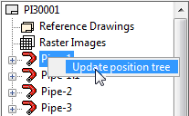
- Select Update Position Tree again. The tree is collapsed.