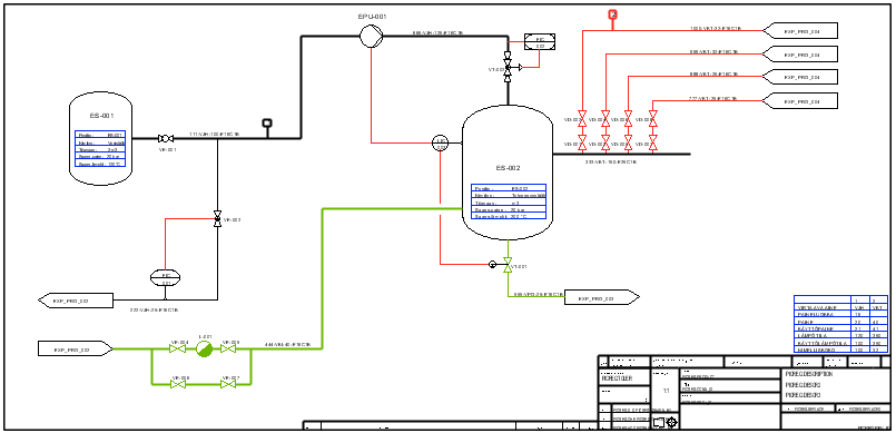
Design Process and Instrument Diagrams
Process and Instrument Design

PI schemas are designed in 2D drawings that are specifically defined as PI schemas. Diagram data is project-specific and the listings are made directly from the project database.
- Diagram lines, diagram arcs, diagram curves, rounded diagram lines, and signal lines can be used when designing a line.
 Diagram Line
 Diagram Arc – Three Radius Points
 Diagram Curve
 Rounded Diagram Line
 Signal Line
 - The properties of a diagram line in a drawing are defined based on the conveyed substance.
For example, if you select the line style Water and Condensate, the line is drawn in green.

You can measure the total distance between the diagram line points.
 Total Distance of Diagram Line Points
 - Components are added to the pipe line. Both the pipe line and any components added to it include technical specifications.
Positions for the pipe lines and components are found automatically according to the desired design rules. Positioning is project-specific.
The pipe line recognizes where it begins and ends. The pipe line data is carried over to components added to the line.
- You can edit the diagram with general element editing functions.
If necessary, you can change the substance conveyed by the pipe line.
- You can import a diagram drawing from another system into Vertex as a file.
- The data from a PI schema is utilized in 3D design. The design data of pipe lines and components in a diagram can be imported into the Vertex G4 Plant Design software. Both the PI and Plant software can use the same databases.
G4 Plant – Process and Instrument Diagram Design without the PI Schema Option
- In the Model window, select Plant> PI Schemas>, and choose one of the following:
Pipes
Equipments
Instruments
Devices
Process Devices
Pumps
Blowers
Vessels
Devices All
Selected all
Setting of corresponding PI/Plant codes
Update data from PI dbases to model
