
Bend Part Data
Advanced Face Modeling Package
General
The dialog box is related to the function
- Part | Deformation |
 Bend Part.
 - Import | | Deformation | Bend Part.
- Bend a Part
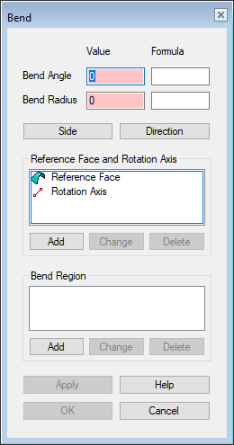
Dialog Box Options
- Bend Angle, Value
- Defines the value of the bend angle.
- Bend Radius, Value
- Defines the value of the bend radius.
- Formula
- Define the formula of the bend radius and bend angle, if you want to control the rotation using a dimension table.
- Side
- The program marks the side to be bent by default with arrows.
- Bending has three options:
- The left side bends from the bending line.
- The right side bends from the bending line.
- Both sides bend. That is, the bend line is in the middle of the bend.
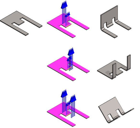
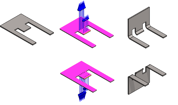
- Direction
- The program marks the default bending direction with arrows.
- The default direction is out of the face.
- Click the Direction button when you want to change the bending direction.
- Reference Face and Rotation Axis
- The reference face is a plane (face), within which the material does not stretch or shrink during bending.
- The material stretches on one side of the face and shrinks on the other.
- Bend Region
- You can limit the bending area. Select the faces/lines (bending area) of the object that you wish the bending function to move. Select the lines from the side of the bend.
 If you have set the bend to occur on both sides, the bending area has no effect.
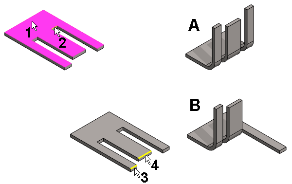
- The planar surface (1) has been selected.
- The rotation axis (2) has been selected.
- The bend angle of 90 ° and the bend radius (10) has been entered.
- The result is shown in the figure A.
- Two lines (3 and 4) has been selected to specify the bend region.
- The result is shown in the figure B.
- Add
- Add a line or reference plane that controls the bend or element that controls the bend region to the list.
-
- Select Add.
- Note that the program uses only one line as the rotation axis and one plane as the reference plane, so adding other lines or planes as a reference plane or rotation axis does not make sense.
- Click the line or planar surface.
- Select Confirm (Confirm = V key, middle mouse button or the context-sensitive function
 OK)
OK)
- Select Add.
- Change
- Replace the selected reference plane or the rotation axis that controls the bend or the element that controls the bend region with another corresponding element.
- Select the element to be changed.
- Select Change.
- Click the replacing element.
- Delete
- Remove the element that controls the bend. However, a reference plane or rotation axis is needed.
- Apply
- Preview by clicking the Apply button in the dialog box. This will show you how the model would look if you confirmed the feature data by clicking OK.