Constrain a Feature Pattern to Dimension-controlled Geometry
Goal
We want to constrain the length or length and width of the pattern to the change in dimensions of a variable part without defining a formula for the length or width of the pattern.
Starting point
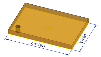
- The part is dimensionally variable, i.e. its dimensions are controlled by variables. Define the Formula Field
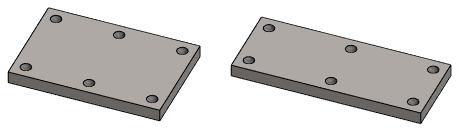
- The part has a feature that we want to form a pattern from.
Pattern
The instruction below describes making a pattern with the context-sensitive function.
You can also create a pattern with the ribbon bar function. See both cases: Linear Feature Pattern
- Select a hole from the part.
- Select the context-sensitive function
 Feature Pattern.
 - Define the feature pattern properties in the dialog box.
 Feature Pattern Data
- Select the
 Linear pattern.
 - Select the default location method of the pattern. Default plane.
- Enter the number of members of the pattern in the length and width direction.
- Enter a short length/width or spacing for the series members.
- Select the
- Confirm the data in the dialog box by clicking OK.
- Position the auxiliary geometry sketch that controls the feature.
- Remove the length and width dimensions of the pattern.
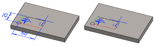
- Add a
 distance between the part geometry and auxiliary geometry
- From the auxiliary geometry, select only two lines between which the constraint is added, for example red and green dashed line.
- Select two points from the auxiliary geometry, between which the constraint is added, so that the sketch does not become overdefined.
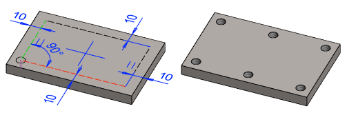
- Select
 OK.
OK. - Test dimensional variation with the context-sensitive function:
 Dimension Table.