Framing Tools: Sheathing
Framer
Tool for the sheathing layer (SHEET, SHEATHING) of a horizontal structure or horizontal structure panel. Select Tool from the list. The parameters are set according to the selected tool. If necessary, edit the parameters in the dialog box. The parameters define the sheet sizes, sheathing direction, alignment, etc. The following sheathing tools are included in the basic software delivery:
- Continuous (CONTINUOUS) - A continuous sheathing style to minimize material waste. The sheathing seams are placed so that the left over parts are utilized in accordance with the spacing of the framing. Parameter Overlap = Spacing.
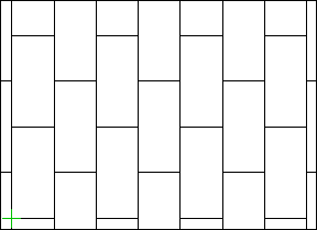
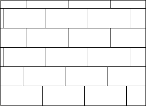
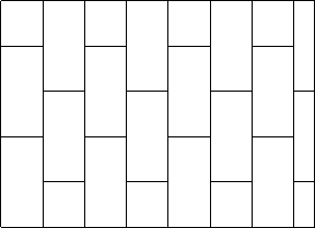
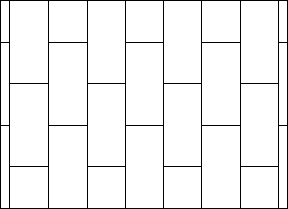
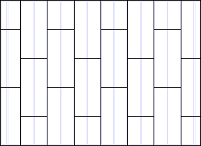
- Staggered (OVERLAP) - This option makes the sheet seams overlap. Parameter Overlap = Half.
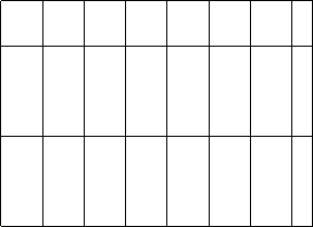
- Grid (GRID) - The sheets are positioned in the sheathing area so that their seams are continuous. Parameter Overlap = None.
Sheathing Rules
- Overlap
- The overlap is set according to the selected tool. If necessary, you can change the overlap.
- Sheet code
- Select a sheet from the list. The sheathing library SHEETLIB may contain several sheets with the same material code but a different size (width x height).
- You can define one of the sheets as the default sheet to be used in horizontal structures. You can define the default sheets by editing the sheathing library with the function System | Structural Libraries |
 Sheathing
 Sheathing. Set the default sheet by selecting the value 1 in the Default field.
 - Gap
- Determine the gap for the seams of the sheathing. Select either of the following:
- Flip
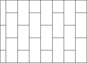
- Select the sheathing angle in relation to the frame layer framing from the list. For example, select the tool Staggered:
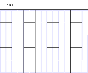
- Align
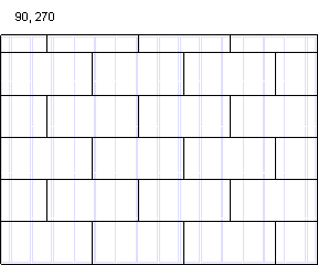
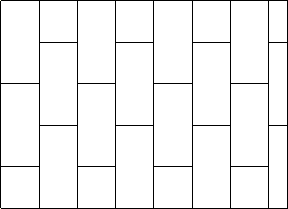
- Select where to start sheathing in the X axis direction. For example, tool Staggered, Angle = 0, Layout direction = From bottom to top.

- Layout direction
- Select where to start sheathing in the Y axis direction. For example, tool Staggered, Angle = 0, Align = Left.

- Offset X, Y
- Enter an offset for the origin of the sheathing area in x and y axis directions. The location of the origin depends on the choices you make in Align and Layout direction. If the sheathing area has been divided into fields, all fields will have the same offset except in the following cases:
- the length of the sheathing area is smaller than the length of the sheet in that direction
- the field is a bracing area