
Edit Truss Parameters Dialog Box
Framer
Select one of the pre-defined parameter sets by clicking the Select button in the Edit Truss Parameters dialog box. This refreshes the parameter values in the dialog box. If necessary, you can edit individual parameters. Select the check box of the parameter you want to edit, and select the desired parameter value. The values of the other parameters will remain unchanged.
Tab: General
- Thickness
- Select the check box, when you want to edit the truss thickness. Enter the desired value in the text field.
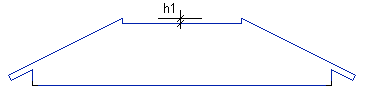
- Hip drop
- Select the check box, when you want to edit the hip drop (h1). Enter the desired value in the text field.
- Ply
- Select the check box, when you want to add a multiple truss. Select one of the following from the list:
- Use
- Select the check box, when you want to edit the purpose of use of the truss. Select the parameter value from the list. The options are customer-specific.
- Function
- Select the check box, when you want to edit the function of the truss. The parameter is used to export truss information to an external truss design software. Select one of the following options:
- Structure
- Select the check box, when you want to edit the structure of the truss. The parameter is used to export truss information to an external truss design software. Select one of the following options:
- Keynote
- Select the check box, when you want to add a remark to the truss. The remark will be displayed in the truss schedule added to the floor plan drawing.
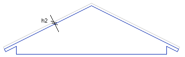
- Top drop
- Select the check box, when you want to lower the top chord. Type the value of the lowering (h2) in the text field.
- Select
- Click the button to select one of the pre-defined parameter sets. Select the parameter set from a list. This refreshes the parameter values in the dialog box.
Tab: Presentation
- 2D visibility
- Select the check box, when you want to edit the method of representation of the truss in 2D drawing. Select either Line or Box as the method of representation.
- 2D properties
- Select the check box, when you want to edit the drawing properties of the truss. The drawing properties define the layer, pen width, line type and color of the lines in the 2D drawing. Type the name of the property set in the text field. The property set needs to be defined in the GEOMPROP keyword group in the system settings.
- 3D visibility
- Select the check box, when you want to edit the method of representation of the truss in 3D model. Select either Line or Volume as the method of representation.
- 3D properties
- Select the check box, when you want to edit the 3D properties of the truss. The 3D properties define the layer, pen width, line type and color of the lines in the 3D model. Type the name of the property set in the text field. The property set needs to be defined in the GEOMPROP keyword group in the system settings.
- Surface properties
- Select the check box, when you want to edit the surface color in the shaded model. The color needs to be defined in the d_LWMAP database.
- Direction symbol
- Select the check box, when you want to show or hide the symbols indicating the viewing directions of the truss in the floor plan drawing. Select either radio button Show or Hide.