Show Geometry Tip in Cursor
You can set the cursor to include a tip window.
- In the 3D window on the elements Point, Line, Face and Part.
- In the sketching mode on the Line element.
Application
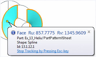
For example, you can use the function to identify surfaces in a model you import into Vertex. You will find the spline faces that prevent geometric constraints from being added to the model.
For example, you will see unfit faces of an Import model, Spline faces, and fix using the Heal function.
 Healing Acis Geometry of a Part Model.
After this, view the model again.
Activating the Geometry Tip
Set the geometry tip either on or off.
- Select
 >
>  User Preferences >
  Drawings, Models.
 - Select View.
- Select Common:
 Show Geometry Tip in Cursor.
- Disable the geometry tip by clearing the check box
 , or by closing the tip window in the working window.
Tip window - Geometry of a 3D model as an example.
When the option is selected, the geometry tip is shown on the following items:
- Part (assembly)
The name of the element is displayed in the Name field of the yip window, if the element has been separately named.

- Point

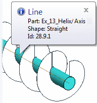
- Line - The element has not been named. The Name field is missing.
- Surface
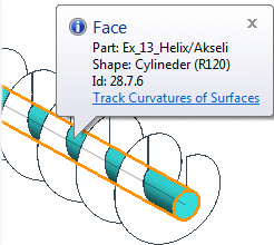
- Face - Track Curvatures of Surfaces - If you select Track Curvatures of Surfaces in the tip window, any face of the editable part can be measured. You can see the curvature lines in the face coordinates by the cursor (below picture). The tip window follows the cursor’s movement. Stop the measurement by pressing the Esc key.
If the tip window disappears when you are trying to select Track Curvatures of Surfaces, zoom or rotate the model in such a way that there is nothing else for the search filter to snap to at the location of the tip window.