
Symbols in Mechanical Drawings
Symbols used in mechanical drawings include part numbers, texts, and manufacturing information, for example welding symbol, surface symbols, etc. You can add the following symbols to a model drawing and to a designed drawing.
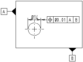
Geometric tolerances
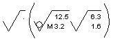
Surface symbols
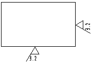
List of surface symbols
Weld symbols
Surface imperfection
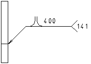
Edge symbol
Texts
Part Numbers
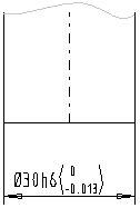
Dimension tolerance
Association of a Symbol
The start point of a reference line is used to associate the symbol with an element in the drawing. When you edit a model drawing, the changes made to the model will be refreshed to the projections of the drawing, and the association of the symbol is retained unless the model geometry will change so radically that a start point of a reference line disappears.
If you click a start point outside of a model projection, the symbol is not associated with any element in a drawing, and does not follow changes made to a model geometry.