
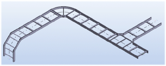
Route Cable Ladder Lines
Model a cable ladder line by drafting the route.
- Add a line by defining the route of the ladder's center line by clicking specific points.
- A cable ladder component is automatically added to locations where the direction changes.
- Model the line close to the actual dimensions. Modify the dimensions with the dimension table. Refine the lengths of the straight sections and their relative positions using geometric constraints.
Add a cable ladder line.
- Select either of the following:
- On the Assembly tab, select Cable Ladder >
 Add Cable Ladder Line.
 - Select the context-sensitive function
 Add > Cable Ladder Line.
- On the Assembly tab, select Cable Ladder >
- On the Cable Ladders tab, in the Properties group, select Class, Nominal size, Item and Elbow Item.
- If desired, select Color from the Component group.Note: The choice of color follows the same principle as the general choice of color for parts. Selecting a color from the old VxColor palette is no longer possible.
- The color is selected in the rendering material dialog box.
- You can select the rendering material by browsing the rendering materials. Old VxColor palette colors can be found in the rendering library folder Vertex palette.
-
You can pick the rendering material from the selected surface.
-
You can restore the default rendering material.
-
You can set the default rendering material for pipe components in the pipe component database d_PIPECOMPONENTS, page 4. If the default rendering material is defined, it is used. Otherwise, the default rendering material of the pipeline is used, which in turn is VxColor_146 by default.
- Old numeric values (referring to the colors in the old VxColor palette) still work in the COLOR field of the database, i.e., a number in the field, e.g. "6", refers to "VxColor_6" in the rendering material library.
- Color selection works in the same way in the G4Plant application for ducts, pipes, cable ladders and platforms.
- If you want, fill in the line position of the cable ladder in the Positions group on the Cable Ladders tab.
- Click the start point of the cable ladder line's center line.
- Define the sweep plane in one of the following ways:
- Select the sweep plane with a context-sensitive function, for example Horizontal(XY) Plane.
- Sweep Plane Based on a Line
- Sweep Plane Based on a Planar Face
- Sweep Plane Based on Three Points
- Define the sweep direction in one of the following ways:
- Constrain the cursor into a ruler.
- Planar Face Normal as a Sweep Direction
- Line as a Sweep Direction
- Do either of the following:
- Use the keyboard to enter the position for the next corner point.
- Before clicking a point you can snap the cursor into a Point, Line or Face on the model if the Snap function is active.

To a Point, Line or Face when the Snap function is active.

- Indicate the corner or end point. Continue modeling the line by clicking the next point.
- You can undo the line to the previous point by pressing Ctrl+Z and then click a different point.
You can undo the added points of the same line all the way back to the starting point.
- When routing the line you can add a component by pressing the B key. Continue routing and accept the component position by selecting Confirm.
- Select Confirm.
Note:
- Pressing the K key shows the directions of the coordinate axes at the cursor.