Loft Using Guide Curves
General
Select two or more surfaces or cross-sections for the loft, and in the Loft dialog box, select the tangency type Guide lines or Virtual guide lines.
- Note that the guide curves must intersect with the edge curve of the cross-section.
Create a loft as follows
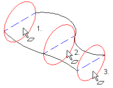
- Sketch the loft section features.
- Add guide lines to the cross-sections at the points where you plan to sketch the guide curves that control the loft. In the example, blue dashed lines.
- Note that the end point of the guide line must be located on the edge curve of the cross-section, so that point can be used to sketch a correct guide curve.
- Cross Section
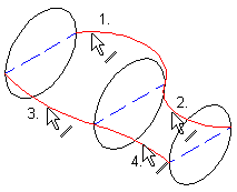
- Sketch the guide curves. A point on the loft section face's edge line has been selected as a guide curve point.
- Note that the guide curve must intersect with the edge curves of the cross-sections.
- In the example image, the (black) guide curves coincide with the endpoints of the cross-sections (blue) dashed lines.
- Guide Curve
- Use Guide Curves in Lofting
- Select the loft section faces in order.
- On the
 tab, in the Lofting group, select
  Boss.
Boss. - Control the loft by the dialog box as selections: Loft Feature Data
- Select tangency to Guide lines. The program prompts you to select the lines of the guide curve.
- Select the lines of the guide curve one by one, and select the function Confirm or
- Select the auxiliary function
 Tangential line chain search and click only the first line from each guide curve.
- Select OK.
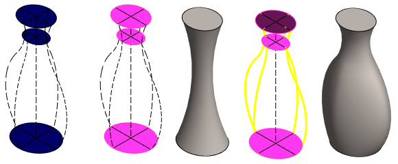
Example
- On the left, a model with three cross-sections and four guide curves.
- Second and third image from the left: The loft is created only on the basis of cross sections.
- Two images on the right: The loft has been corrected by adding guide curves.