
Requirements for Guide Curves Used in a Loft
Things to consider when modeling the guide curve used for lofting
- The guide curve must be a tangential line chain.
- The guide curve must intersect the edge line of the cross-section surface.
- This is achieved by constraints when sketching cross-sections and guide curves.
- You can use several guide curves in lofting.
- The guide curve can extend past the first and last cross sections, but the lofting ends at the cross sections.
Example
In this example, the guide curve is sketched first and then the cross sections.
First sketch and the operation Guide curve:
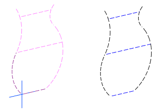
- The bottom horizontal line and the arc in the lower left corner start from the origin of the model.
- The guide lines used for lofting are shown in the image as black dashed lines.
- The guide lines used for cross-sections are shown as blue dashed lines.
- The endpoints of the blue lines coincide with the arc lines.
Second, third and fourth sketch and the operation Cross section.
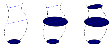
- The edge line of each cross-section is consistent with the endpoints of the blue guide lines in the first sketch.
- The cross-section of the base is drawn in the Horizontal (XY) plane.
- The sketch plane of the second and third cross-sections is defined by selecting the lowest cross-section and the end point of the blue dashed line and the context-sensitive function New Sketch.
Loft
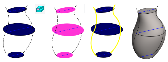
- The function Part | Lofting |
 Boss
Boss - First, three cross-sections are selected in order from bottom to top (or vice versa).
- The Confirm function completes the selection of surfaces and opens the Loft dialog box.
- Loft Feature Data
- Then the Tangency type is selected: Guide lines.
- OK.
Note: If the tangency type Guide lines does not give the desired result, then try changing it to Virtual guide lines.