Wall 3D Volume Properties
Select the general properties of a wall layer in the dialog box. Open the dialog box as follows:
- Double-click a wall. The Wall dialog box opens.
- Select a layer in the list or in the preview image.
- Right-click to open the context-sensitive menu.
- Select Properties. The Wall 3D Volume Properties dialog box opens.
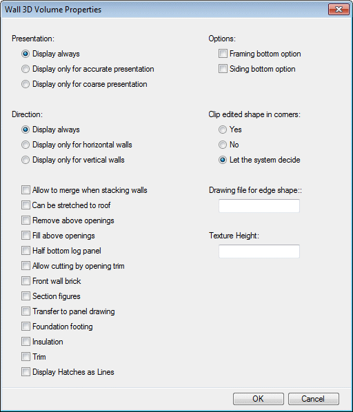
Dialog Box Options
- Instance
- Select one of the following as the Wall 3D Volume presentation method:
- Direction
- Select one of the following:
- Allow to merge when stacking walls
- When the volume has this property (MERGE), it can be merged with the corresponding volume of a wall above or below it.
- Can be stretched to roof
- When the volume has this property (STRETCH_TO_ROOF), it can be stretched to a roof above
it by using the
 Clip
Siding with Roof Automatically.
 - Remove above openings
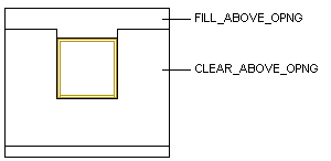
- Select this property (CLEAR_ABOVE_OPNG) for the siding layer. When the siding layer has this property, the siding can be removed from above openings when you are adding or editing an opening. You can select siding above openings by selecting the Fill Above Openings (FILL_ABOVE_OPNG) property.
- Fill above openings
- Select this property (FILL_ABOVE_OPNG), for example, for board lining above brick siding. When the brick siding has the Remove Above Openings (CLEAR_ABOVE_OPNG) property, it can be removed from above an opening when you are adding or editing an opening. You can add siding with the Fill Above Openings property (FILL_ABOVE_OPNG) above the opening.
- Half bottom log panel
- Select this property (HALF_LOG) for paneling. When paneling has this property, the height of the lowest panel is half of a panel.
- Allow cutting by opening trim
- Select this property (ALLOWCUT) for the siding layer. When the siding layer has this property, siding will be removed from the trim area of an opening.
- Front wall brick
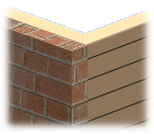
- Select this property (FRONT_BRICK) for the brick siding of a gable wall. When the siding layer has this property, the brick siding will reach the outside edge of the side wall in the model.
- Section figures
- You can select this property (AUTOSECTION) for any layer you wish. When the volume has this property, a cross section hatch will be added for it in the vertical cross section created from the building's 3D model. You can select the cross section hatch by selecting the cross section property for the layer. Drawing the cross section hatch requires that the SECT_DRWFIG property has been defined for the project.
- Transfer to panel drawing
- You can select this property (TO_PANELDWG) for the siding layer. When a volume has this property, its outlines can be drawn on the wall panel drawing. Drawing the outlines requires that drawing of front elevation siding on the panel drawing be defined in the wall panel settings.
- Foundation footing
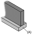
- The property (FOOTING) defines the shape of the footing at the end of a foundation wall. Select the property for the footing volume (A) of the foundation wall.
- Options
- You should select a property for the framing or siding layer of a wall that allows a volume to be stretched when a certain optional condition is met.
- Clip edited shape in corners
- This property (CORNER_CLIP) determines how a layer with an edited shape is trimmed in a corner. The effect of this property can be seen in the 3D model of the building. A layer with an edited shape can be, for example, a siding layer stretched across a corner. The Let the System Decide is the default option (A in the sample figures), where the distance of the stretched layer's edge from the corner determines whether the layer is trimmed to the corner or not.
- Drawing file for edge shape
- Select this property (BORDER), for example, for siding with vertical boards. The bottom edge of the siding is machined with a 2D hatch. Draw the basic hatch shape (A) and save it as a drawing file in the folder ../custom/macros/walls. Enter the name of the drawing file in the text field. The program will generate a continuous polyline by copying the basic hatch shape repeatedly, and use it to machine the bottom edge of the siding.
- Height of texture
- Select this property (H) for the panel siding layer. Enter a height value for the hatch texture in the text field.
- Display Hatches as Lines
- When this property is selected, the hatch of the layer is exploded to lines. This enables you to snap to the line points.




 If the hatch is dense, a lot of
lines are created. This may make the model slower to handle.