
Set the Visibility of a Building Component in Drawing-Model Pairs
By default, the geometry of a building component is shown in one drawing-model pair only: the one it is added in or moved to. If necessary, you can set the components visible also in other drawing-model pairs. For example, you can show columns, beams and chimneys in both architectural and framing model. Similarly, you can show a grid or section symbols in the floor plans of desired floors.
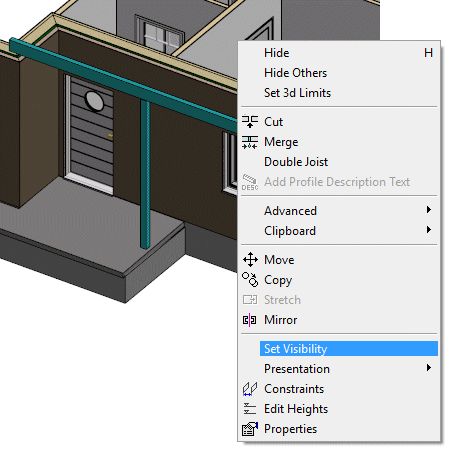
- Select one or more building components.
- Right-click to open the context-sensitive menu.
- Select Set Visibility.
The Select Drawing-Model Pairs dialog box opens. Drawing-model pairs are grouped by the floors of the building in the dialog box.
The drawing-model pair in which the original geometry of the component is, is greyed out. You cannot change the visibility of the building component in this drawing-model pair.
- Select the drawing-model pairs in which the geometry of the building component will be shown.
- Confirm by clicking OK.
 Note
Note
- The customer-specific template project does not necessarily have a "Foundation, framing" drawing-model pair. However, the drawing-model pair is necessary if you wish to set the foundations visible in the framing model. Add the drawing-model pair, if necessary: Example: Framing Drawing-model Pair of Foundations.