
Drawing-Model Pairs
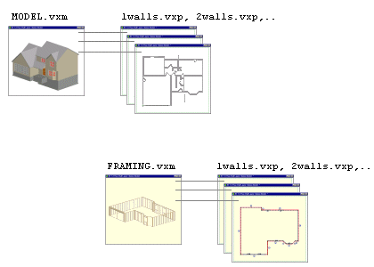
A building can be divided into parts, for example by floors. Each part is designed in its own drawing-model pair. A drawing-model pair contains one drawing file (*.vxp) and one model file (*.vxm). A model file can form a pair with several different drawing files, and vice versa. The model file may be either of the following:
A project may contain several drawing files, for example
|
 |
In Architectural Design, the drawing-model pairs consist of drawing files, to which a MODEL.vxm model file is connected. In structural design, the FRAMING.vxm model file is connected to the drawing files. You can create new drawing-model pairs and edit the existing ones. You can browse the drawing-model pairs of an open project in the document browser.
 Note
Note
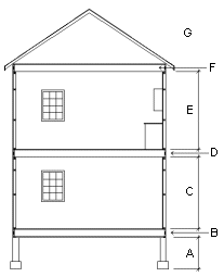
- The default heights and default dimensions of structural components are separately defined for each floor of the building, see Parameters of Different Floors.
You can tell apart the drawing-model pairs used in architectural design and framing by viewing the icon at the top left corner of the working window.
 - The architectural design drawing-model pair is active.
 - The framing drawing-model pair is active.