
Graphics Settings
Define the graphics settings by selecting  >
>  Preferences >
  Graphics. Settings are workstation-specific.
Click Apply to preview the effect of changes on the graphics drawing.
Dialog Box Options
- Part highlight transparency
- Defines the percentual transparency of an object selected in the working window. Transparency is not used with the default value of 0 %.
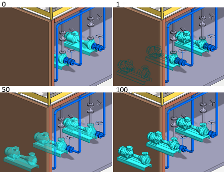
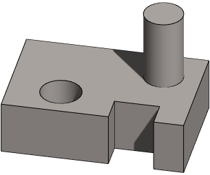
- Highlight alpha blending
- Adjustment of the visibility of the selected object and the geometry in front of it. With a value of 0, the geometry in front covers the selected object. With a value of 1, the edge lines of the selected object are visible through the geometry in front of it. With a value of 100, the selected object covers the geometry in front of it. With other values, the selected object is partially visible through the geometry in front. In the example figure, the transparency of the selected part is set to 0.
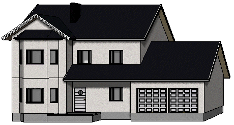
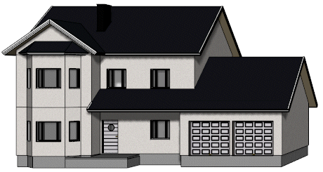
- Anti-aliasing
- The anti-aliasing smooths out the jagged edges on the screen. If you change the value, restart the program. When the value is 0, anti-aliasing is disabled:
- Shadow strength
- Defines the darkness of shadows (0-5). When the value is 0, shadows are not drawn at all.
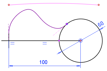
- Curve density
- Vertex G4: Defines how accurately curves (circles, splines, etc.) are drawn in sketching, and the control curve in part and assembly models. With lower values, performance improves, with higher values, quality improves.
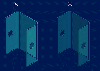
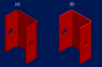
- Draw edges
- Edges of a part will be visible when the model is stationary in the working window. If the feature is disabled, edges will not be drawn when the model is stationary. Compare the drawing of a part: edges drawn (A), and edges not drawn (B).
- Draw textures
- Material textures are displayed in the OpenGL shaded model. It is required, that the color shader of the material is of the type Wrapped Image. Wrapped Image is a color type that fills an area with an image file.
- Draw cross sections to 3D limits
- The feature is effective when the model is limited with planar faces. When the feature is disabled, the cross sections are drawn in the limited 3D model. The 3D limiting of a large assembly is quicker, if you clear the checkbox.
- Draw non-editable geometry as grayed
- Vertex G4 Plant: It is easier to view large assemblies if you enable the property. Geometry that has been selected for editing is more clearly visible in the model, especially if it is shown in some other color than gray.
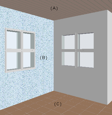
- Background color
- Select a background color for the drawing and model window. You can set a graduated background color for the model by selecting a color for both the top and bottom edges of the window. The background color is solid when both colors are the same. In addition, you can select a background color for a sketch (Vertex G4).
- Use environment image as background
- Select the environment image added in the model as the background for the model or sketch. This requires, that the Rendering add-on feature is available.
- You can add the environment image by using the function Rendering | Environment |
 Environment Image.
 - Wireframe
- Select the color by which the lines are drawn in the model's wireframe presentation. With Default, the lines match the colors of the materials.
- Apply
- Click Apply to preview the effect of changes on the graphics drawing.