
Export IFC Model Dialog Box
IFC Converter
Select the settings according to which the building model is exported to an IFC file. You can use the same settings for the building model again later when you save the selected settings as a template. The template is saved in the building-specific component library. If necessary, you can copy the template to the customer-specific component library, in which case it is also available for other building models.
Export template
- Select template
- You can select the export settings by selecting a ready-made template from the list. The template can be stored in a building-specific component library, a customer-specific component library, or a system component library. The component library included in the standard delivery of the program has two ready-made templates.
- Save template
- You can save the settings selected in the dialog box as a template in the building-specific component library by clicking Save template. Type a name for the template in a text box. All the selected settings are saved in the template, except for the file path of the IFC file.
Objects
- How do you want to select what to export
- If you started the function by selecting objects from the building model and Export to IFC from the right-click menu, the Export selected option is selected and no other options are available. In this case, only the selected objects are exported to the IFC file.
- If you started the function
 >
>  Export >
  IFC Export, select one of the following:
- Export visible - Objects visible in the building model are exported to the IFC file, regardless of which floor they are on or what object type they are. If you have hidden objects from the model, they are not exported.
- Filter by object type - Objects that are of the type selected under Object types to export are exported to the IFC file, regardless of whether they are visible in the building model or not. Under Model storeys to export, you can select the floors from which the objects are exported.
- Model storeys to export
- When the option Filter by object type is selected, you can select the floors from which the objects will be exported to the IFC file. Click Select all to select all or clear all selections.
- Object types to export
- When the option Filter by object type is selected, you can select the object types to be exported to the IFC file. Click Select all to select all or clear all selections.
Settings
- Export model to
- The IFC file corresponding to the name of the building is saved in the IFC folder in the building's folder when Building - IFC folder is selected. You can edit the name of the file in the File path field.
- Export property sets
- Select the property sets according to which data is transferred from objects to the IFC file.
- IFC standard common property sets
- Vertex property sets
- User defined property sets
- Sub model handling
- If the building model has a sub model with objects in different floors, select how the floor of the sub model's objects is determined in the IFC export:
- Export sub model part storeys according to heights - A default choice that works in most cases. In the IFC model, the floor of the object is determined based on height differences. Example:
- The sub model has objects on the 1st and 2nd floor. It is added to the 2nd floor in the main model. The main model is exported to an IFC file. In the IFC model, the objects of the sub model are on the 2nd and 3rd floor.
- Export sub model storey as IFC Storey - In the IFC model, the floor of objects is the floor to which the sub model is added in the building model. Example:
- The sub model has objects on the 1st floor and 2nd floor. It is added to the 2nd floor in the main model. The main model is exported to an IFC file. In the IFC model, all objects of the sub model are on the 2nd floor.
- Export sub model part storeys according to heights - A default choice that works in most cases. In the IFC model, the floor of the object is determined based on height differences. Example:
- Select how sub model objects are exported to the IFC model hierarchy:
- Export sub models as separate models - In addition to the main model, a separate IFC file is created for each sub model. The objects of the sub model are exported to the IFC model like other objects in the building model. In the example figure, the main model consisting of two sub models has been exported to an IFC file. Objects appear in the IFC model tree as usual.
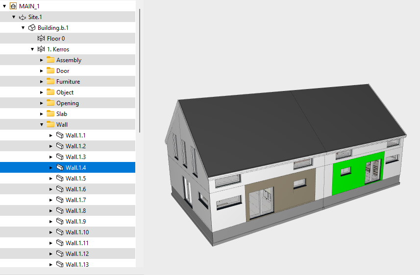
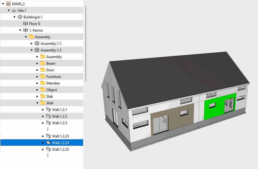
- Export sub models as assemblies - The sub model is exported to an IFC file as an assembly. In the example figure, the main model consisting of two sub models has been exported to an IFC file. Sub models appear in the IFC model tree as assemblies Assembly.1.1 and Assembly.1.2, and objects appear under these assemblies.
- Export sub models as separate models - In addition to the main model, a separate IFC file is created for each sub model. The objects of the sub model are exported to the IFC model like other objects in the building model. In the example figure, the main model consisting of two sub models has been exported to an IFC file. Objects appear in the IFC model tree as usual.
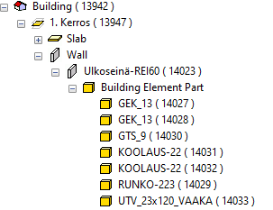
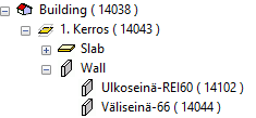
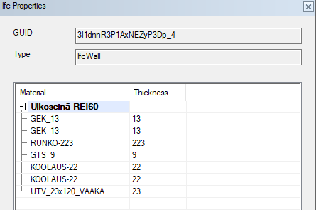
- Layer handling
- Select how the wall layers are exported to the IFC model.
- Edit project info
- If necessary, edit the building data to be written to the IFC file by clicking Edit project info. This function opens a dialog box with fields on the left showing the information to be written to the IFC file. The fields on the right show the information to be read from the archive. When you open the dialog box for the first time, the contents of the fields are the same on both the left and right. You can edit the contents of the fields to be written to the IFC file. Fields with different contents in the IFC file than in the archive are highlighted in a different color. You may have edited the information that is written in the IFC file, or the building data has changed in the archive. You can select the following functions:
- Update - Update the information to be written in the IFC file to match the data in the archive.
- Clear - Clear all fields to be written in the IFC file.
Coordinates
- Move exported objects according to
- Select the point that will become the origin point of the IFC model.
- Model origin - The origin point of the model becomes the origin point of the IFC model.
- Site origin - The origin point of the site becomes the origin point of the IFC model.
- Origin of imported IFC model - If one IFC model has been imported into the building, and the placement options IFC site origin is positioned on Vertex site origin or IFC model origin is positioned on Vertex origin, you can select the origin point of the imported IFC model as the origin point of the exported IFC model.
- A point in the model - Enter the coordinates of the point in the fields, or select a point from the floor plan or model by clicking 2D or 3D under Select a point from.
- Rotate to north direction
- If the north direction has been defined in the building coordinates, you can rotate the building to the north direction (y axis parallel to north direction) by selecting Rotate to north direction. You can also use the feature to rotate the geometry of the building by entering a rotation angle in the field. The angle is calculated in the clockwise direction starting from the positive y-axis.
Note: Setting the coordinates and height of the site origin and the north direction, see Building Coordinates and Heights.