
Position a Part in an Assembly
You can add parts to the assembly that have been modeled using the following software:
- Vertex G4 Mechanical Engineering.
- Other CAD software, provided that the model has been saved as a Vertex model.
Creating an Assembly
Before you begin creating an assembly, reserve a new model number for the assembly in the archive.
- Select assembly as the model type.
- Enter the preliminary Archives Data for the model. This can be supplemented later.
- After this, a working window will be displayed for creating the assembly. The model number will be displayed in the assembly tree to denote the assembly.
Building an Assembly
You can build an assembly using the following part types:
- Modeled, archived parts, which can be added to the assembly from the archive.
- Local parts, which can be modeled in the assembly model.
As an example, a guide curve of a profile, or other simple part, drawing not needed.
- Ready-made components, which can be selected from the library.
For example, assembly component (profile).
 The first part of the assembly will not be positioned in the origin of the assembly always. This happens only if you create a new part in the blank assembly. If you add the first part in the assembly, position the part using V key or by the middle mouse button, and the part is positioned in the origin.
Set the model origin by the function  Model Origin Visible
To position parts accurately in the assembly, you need to determine the geometric constraints between them.
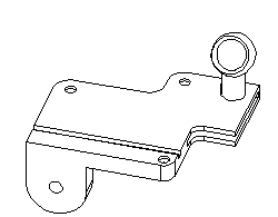
The First Part in an Assembly
The part added to the assembly first is the start-up part, which will remain stationary.
- The insertion point of the first part is the origin of the assembly if you position the part by the V key or middle mouse button.
- Other parts can be added to the assembly after adding the start-up part.
Parts and geometric constraints can be edited and deleted while building the assembly.
It is a good idea to have the start-up part as close to being finished as possible, so that you do not need to repeatedly change the geometric constraints between the parts due to changes made to the start-up part.
Adding a Part to an Assembly
You can build an assembly by adding parts that have already been modeled.
- Select the part from the archive. Selecting the right part is made easier with the Preview function. If configurations are determined in the part, you can select a configuration.
- A part that has been added to an assembly will include a link to the original model. You can select a part from an assembly and open it for editing. Note, the changes made in the part will be saved as the archives model. Thus, changes to a part will affect all assemblies in which the part in question has been used.
Other parts have been added to the assembly besides the start-up part. You can position the parts in an assembly by using geometric constraints.
Copying a Part
You can add more than one copy of the same part to an assembly.
Any part can be copied in the assembly to a new location after selecting the part. For example, using Copy and Paste.
When a part has been archived and added to an assembly once, it can later be copied from and added to an assembly. After adding a part, position it in the assembly using geometric constraints.
Modeling a Part in an Assembly
In an assembly you can model local parts or model parts and save in the archives. Position the part in the assembly using geometric constraints. You can bind sketches in the assembly to a visible geometry using geometric constraints.
By default, the parts is fixed. You can bind the part using geometric constraints in their positions.
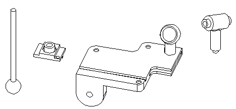
Adding Library Components to an Assembly
You can add components like bolts, for example, to an assembly from the component library. Select the component from an image menu, in which the component types are depicted as thumbnail images.
A component can be positioned as follows:
- aloft (click some place in the working window). Geometric constraints not added.
- To face, line or point. Geometric constraints are added between parts.
For example, position the screw to the center point of the hole on a volume.
Positioning a Subassembly
A subassembly can be added to an assembly just like a part. It can be opened from the archive and positioned in the assembly. The exact position of the subassembly will be defined by the geometric constraint that you set between the start-up part of the subassembly and a part in the assembly.
When dealing with large assemblies with a number of parts, you can hide parts of the subassembly. This way, you can position the subassembly more quickly. The subassembly parts used to determine the position must be displayed.